
Protective temperature helmet and shoulder pads, protective temperature helmet and shoulder pad liner

a technology of protective temperature helmet and shoulder pad, which is applied in the field of shock absorption helmet lines, can solve the problems of poor design of helmet and helmet liners, player's incredibly prone to concussion, etc., and achieve the effects of eliminating physical shock, preventing brain swelling, and light weigh

Inactive Publication Date: 2016-12-01
HARTY ROBERT D
View PDF4 Cites 7 Cited by
  • Summary
  • Abstract
  • Description
  • Claims
  • Application Information

AI Technical Summary

Benefits of technology

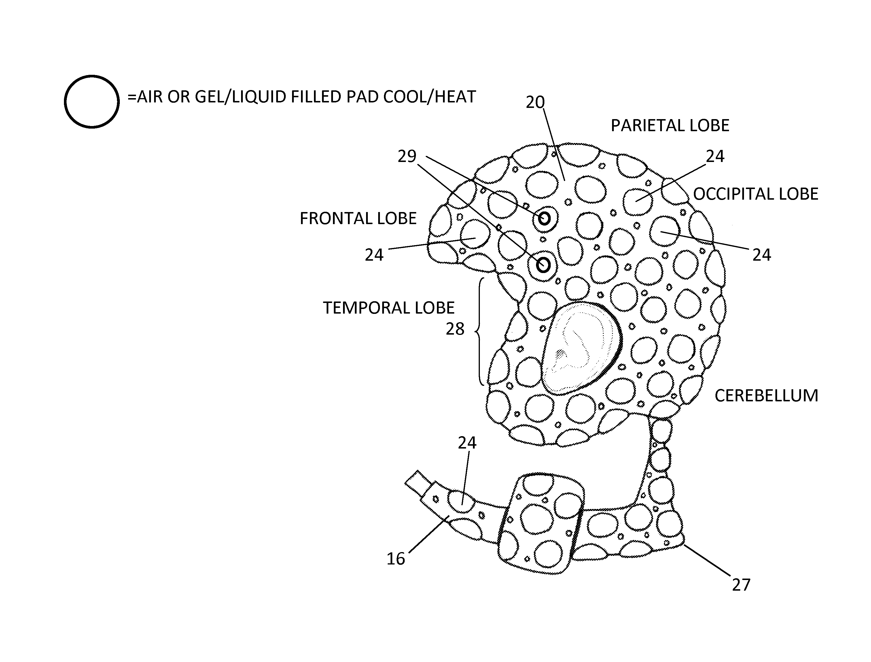
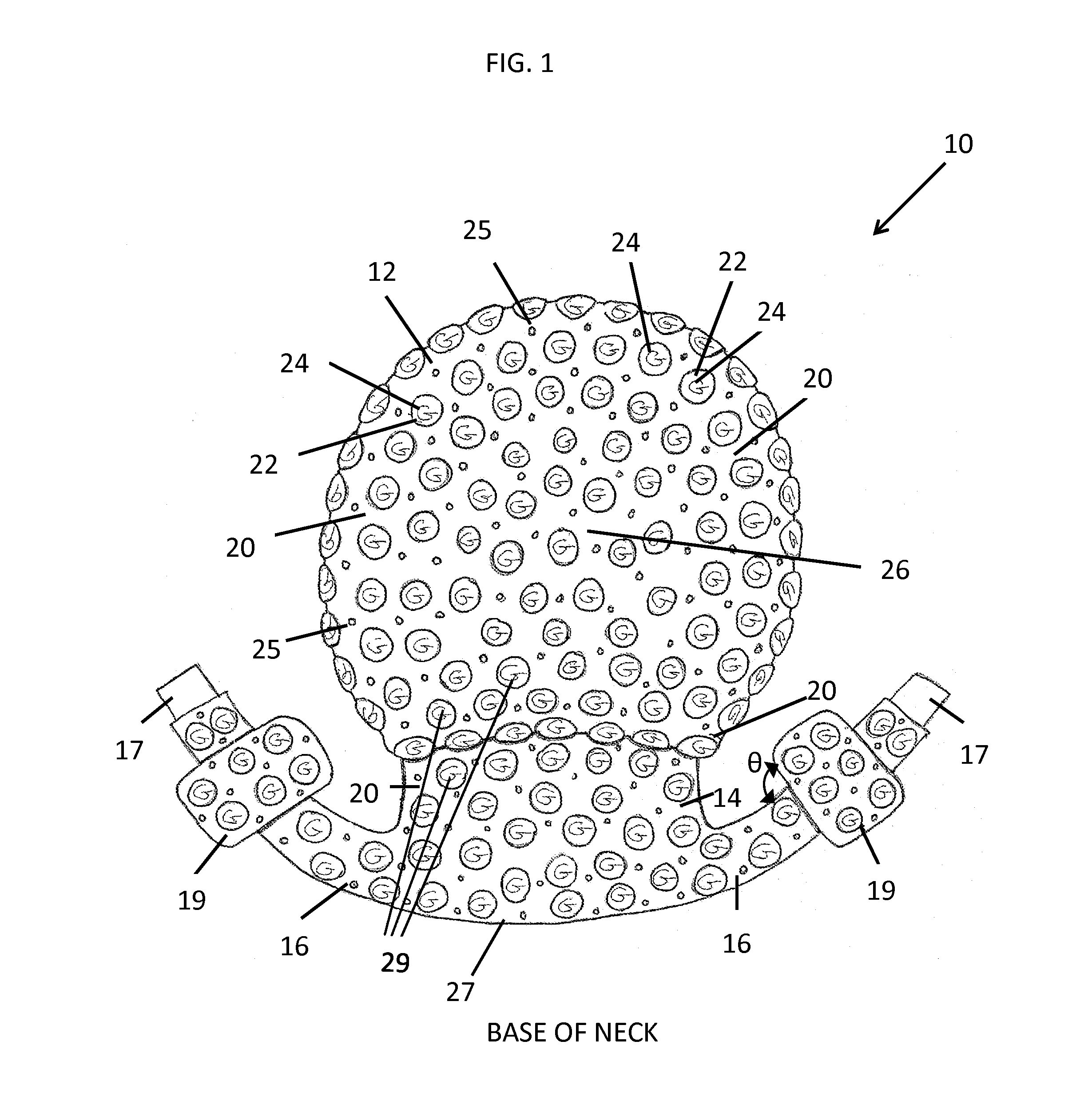
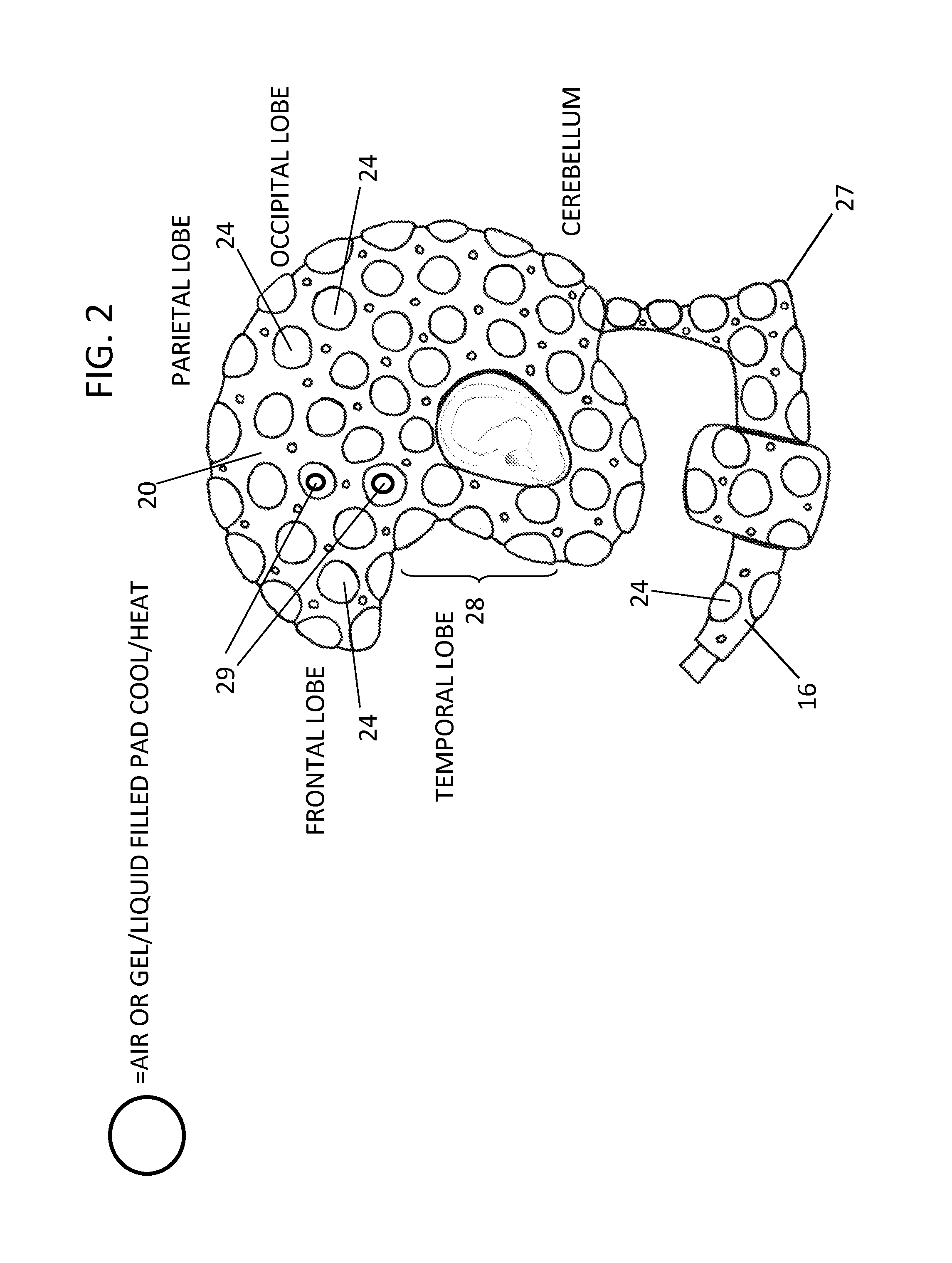
The present invention provides a head cooling / heating device that can be used to prevent concussions and brain swelling on overheated players. The device consists of a webbing that can be cooled or heated and a plurality of cavities that can receive cooling or heating substrates. The substrates can be cooled or heated before being inserted into the cavities. This device can be used as a standalone head protection or in combination with standard protective headgear. The webbing can be pre-filled with cooled or heated fluids, eliminating the need for additional fluid containers. The device can also include a temperature indicator to quickly determine if the player is at risk of overheating and brain swelling. Overall, this invention provides a lightweight, effective solution for managing brain temperature and protecting players from heat-related injuries.

Problems solved by technology

A majority of concussions sustained by persons involved in contact sports are the result not only of hard blows, but also from poor designs of the helmets and helmet liners.
In such scenarios, the brain may potentially move closer to the cranium or actually make contact the cranium, This makes the player incredibly prone to concussion inasmuch as the 10 cc of cushioning space mentioned supra is gone.

Method used


Image

  • Protective temperature helmet and shoulder pads, protective temperature helmet and shoulder pad liner
  • Protective temperature helmet and shoulder pads, protective temperature helmet and shoulder pad liner
  • Protective temperature helmet and shoulder pads, protective temperature helmet and shoulder pad liner

Examples


Embodiment Construction

[0029]The foregoing summary, as well as the following detailed description of certain embodiments of the present invention, will be better understood when read in conjunction with the appended drawings.

[0030]As used herein, an element or step recited in the singular and preceded with the word “a” or “an” should be understood as not excluding plural said elements or steps, unless such exclusion is explicitly stated. Furthermore, references to “one embodiment” of the present invention are not intended to be interpreted as excluding the existence of additional embodiments that also incorporate the recited features. Moreover, unless explicitly stated to the contrary, embodiments “comprising” or “having” an element or a plurality of elements having a particular property may include additional such elements not having that property.

[0031]The invention provides a device for both cooling and protecting and cushioning the brain, both functions occurring simultaneously. Starting with a webbin...


PUM


Abstract

The invention provides head, neck, chest, and spine logical impact protection and thermal-regulation device having a webbing adapted to encapsulate head and neck, wherein the webbing is composed of a plurality of reversibly deformable substrates that are capable of being cooled or heated; wherein the webbing further provides apertures interspersed between the reversibly deformable substrates to allow fluid exchange between the head, neck, chest, and spine and the regions exterior to the webbing; and a temperature indicator, wherein the temperature indicator measures the temperatures of the body surface underlaying the webbing.

Description

CROSS REFERENCE TO RELATED APPLICATIONS[0001]The instant application claims priority as a continuation in part of U.S. patent application Ser. No. 13 / 354,202, filed on Jan. 19, 2012, issuing as U.S. Pat. No. 8,943,617 on Feb. 3, 2015.[0002]U.S. patent application Ser. No. 13 / 354,202 claimed priority both as a non-provisional application of U.S. Provisional Patent Application Ser. No. 61 / 434,281 filed on Jan. 19, 2011, currently expired, and also as a continuation in part of U.S. patent application Ser. No. 12 / 982,621, filed on Dec. 30, 2010, issued as U.S. Pat. No. 8,468,613 on Jun. 25, 2013, the entirety of which is incorporated by reference, which in turn is a continuation in part application to U.S. patent application Ser. No. 10 / 687,182, filed on Oct. 16, 2003, issued as U.S. Pat. No. 7,861,326 on Jan. 4, 2011.BACKGROUND OF THE INVENTION[0003]1. Field of the Invention[0004]This invention relates to a shock absorbing helmet liner which simultaneously keeps the wearer's head and n...

Claims


Application Information

Patent Timeline
IPC IPC(8): A42B3/12A63B71/12A63B71/10A42B3/04A61B5/01
CPCA42B3/128A42B3/0473A61B5/01A61F2007/0012A63B71/1291A61B2562/0276A63B71/10A42B3/121A42B3/285A41D13/0512
Inventor HARTY, ROBERT D.
Owner HARTY ROBERT D
Learn More