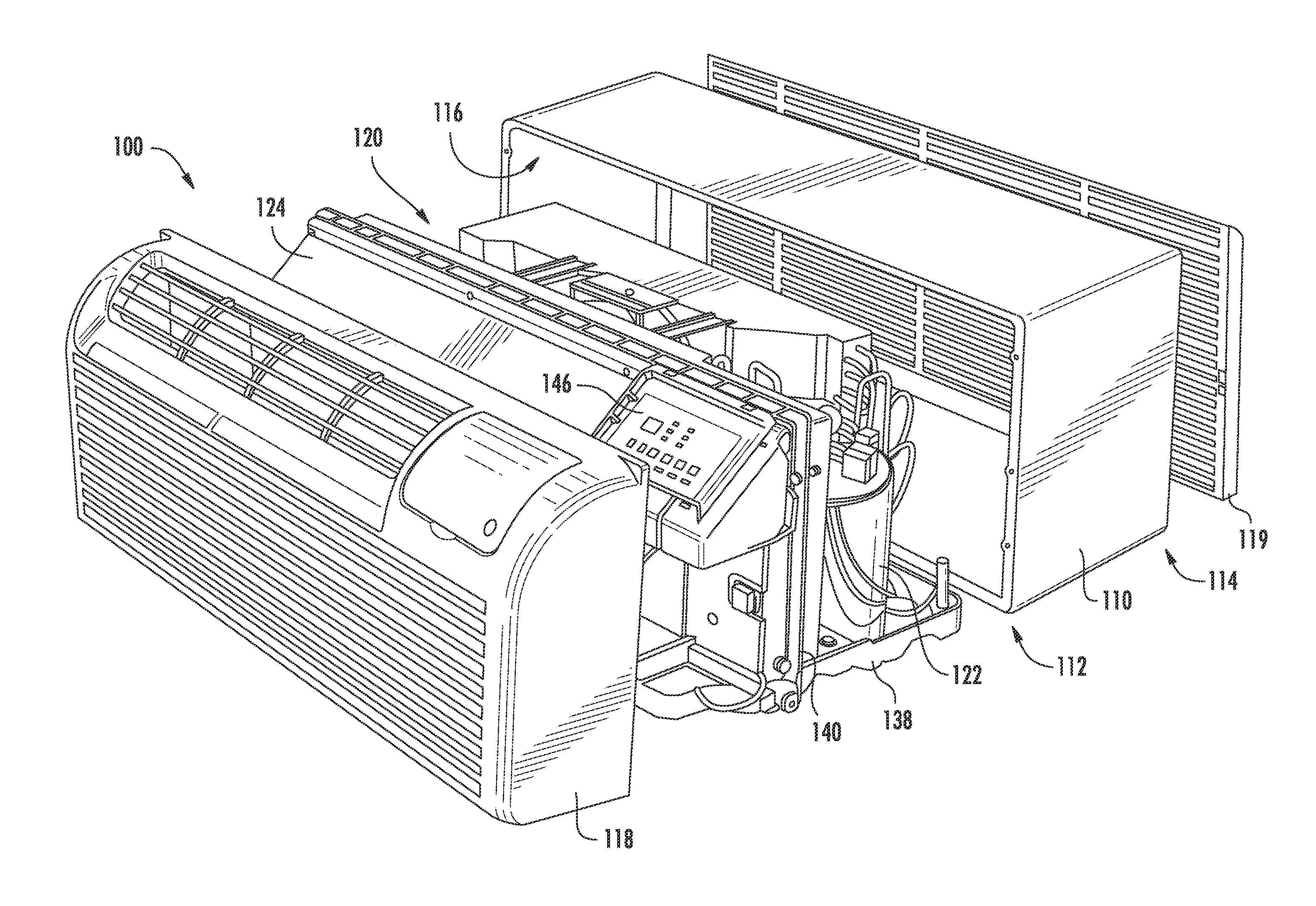
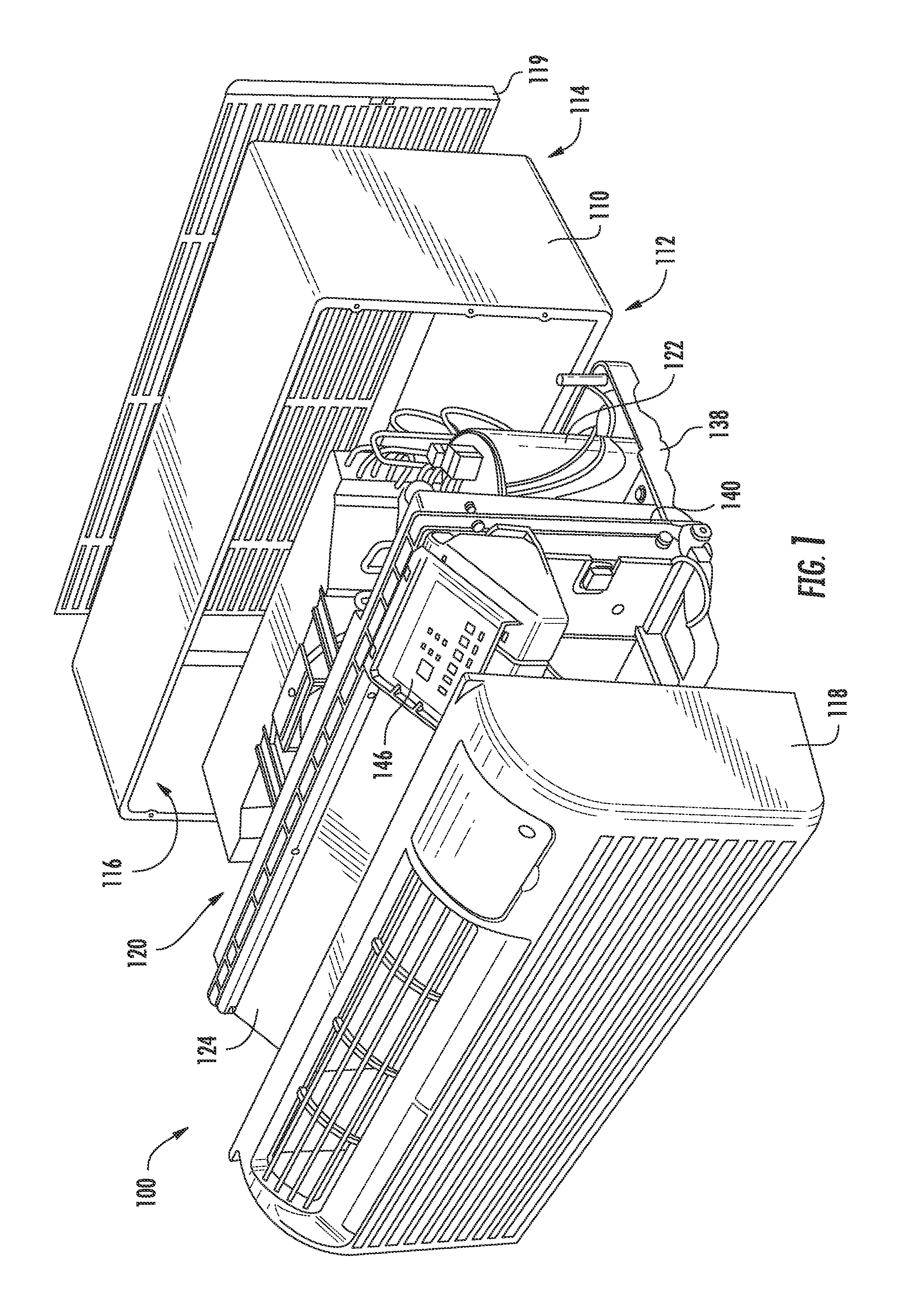
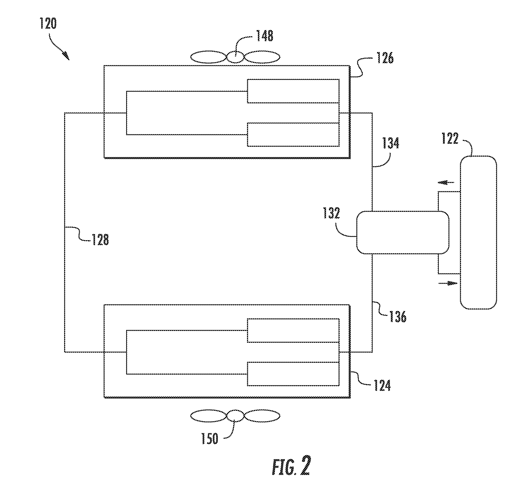
Packaged terminal air conditioner unit

a terminal air conditioner and packaged technology, applied in the field of heat pump systems, can solve the problems of unwieldy and inefficient wire configuration, difficult to secure wire configuration within the confines of the packaged terminal air conditioner unit,

Active Publication Date: 2016-12-15
HAIER US APPLIANCE SOLUTIONS INC
View PDF20 Cites 2 Cited by
  • Summary
  • Abstract
  • Description
  • Claims
  • Application Information

AI Technical Summary

Benefits of technology

[0004]One example aspect of the present disclosure is directed to a packaged terminal air conditioner unit. The packaged terminal air conditioner unit comprises a casing, a compressor positioned within the casing, an interior coil positioned within the casing, an exterior coil positioned within the casing opposite the interior coil, and one or more associated power relay coils. The packaged terminal air conditione...

Problems solved by technology

Such sealed system components may be coupled to a circuit board in the packaged terminal air conditioner unit using complicated and/or costly wire configurations.
Such wire configu...

Method used


Image

  • Packaged terminal air conditioner unit
  • Packaged terminal air conditioner unit
  • Packaged terminal air conditioner unit

Examples


Embodiment Construction

[0017]Reference now will be made in detail to embodiments of the invention, one or more examples of which are illustrated in the drawings. Each example is provided by way of explanation of the invention, not limitation of the invention. In fact, it will be apparent to those skilled in the art that various modifications and variations can be made in the present invention without departing from the scope or spirit of the invention. For instance, features illustrated or described as part of one embodiment can be used with another embodiment to yield a still further embodiment. Thus, it is intended that the present invention covers such modifications and variations as come within the scope of the appended claims and their equivalents.

[0018]Example aspects of the present disclosure are directed to a packaged terminal air conditioner unit. The packaged terminal air conditioner unit can include a jumper harness associated with the packaged terminal air conditioner unit. Such jumper harness...


PUM


Abstract

A packaged terminal air conditioner unit is provided. The packaged terminal air conditioner unit can include a heater bank jumper configured to couple one or more heater banks to a controller associated with the packaged terminal air conditioner unit. The heater bank jumper can be selectively configurable to provide at least one shunt line to couple at least one contact point associated with the controller to at least one contact point associated with the one or more heater banks. In this manner, the heater bank jumper can be configured based at least in part on an amount of current provided to the packaged terminal air conditioner unit by an electric service.

Description

FIELD OF THE INVENTION[0001]The present subject matter relates generally to heat pump systems, such as packaged terminal air conditioner units, and sealed systems for the same.BACKGROUND OF THE INVENTION[0002]Certain packaged terminal air conditioner units include a sealed system for chilling and / or heating air. The sealed systems include various components for treating a refrigerant in order to cool or heat air. The sealed system components are generally positioned within a casing that can be mounted within a wall or window of an associated building. The sealed system can generally include a controller configured to control one or more of the sealed system components. Such sealed system components may be coupled to a circuit board in the packaged terminal air conditioner unit using complicated and / or costly wire configurations. Such wire configurations can be unwieldy and inefficient. In addition, such wire configurations may be difficult to secure within the confines of the casing...

Claims


Application Information

Patent Timeline
IPC IPC(8): F25D23/10F25B13/00F24F1/032
CPCF25B13/00F25D23/10F24F1/032
Inventor ANGLE, JEFFREY ALANDUPLESSIS, SAMUEL VINCENTHENDERSON, RICHARD DUSTINBEILFUSS, ROBERT CHARLES
Owner HAIER US APPLIANCE SOLUTIONS INC
Why Eureka
Try Eureka