
Device and method for painting curved outer surfaces of an aircraft

a technology for aircraft and outer surfaces, applied in process and machine control, program control, instruments, etc., can solve the problems of affecting the and requiring a very long production time. , to achieve the effect of shortest production time and durable application of high-quality picture moti

Inactive Publication Date: 2016-12-22
AIRBUS OPERATIONS GMBH
View PDF5 Cites 0 Cited by
  • Summary
  • Abstract
  • Description
  • Claims
  • Application Information

AI Technical Summary

Benefits of technology

The invention provides a device and method for painting the curved outer surface of an aircraft with high-quality picture motifs in the shortest possible production time. The use of PUR aircraft paint results in a highly durable bond between the paint layers and achieves a high level of resistance. The invention also utilizes spray painting technology, which allows for larger surfaces to be provided with a picture motif of sufficient resolution in a shorter period of time than inkjet technology. The positioning device for the invention may be realized in the form of a gantry robot or a multi-axis articulated robot, depending on the needs of the application.

Problems solved by technology

In this technical solution, it appears disadvantageous to utilize pigment ink that does not adhere to the outer surface in a very abrasion-resistant fashion despite the hardening process.
During the operation of the aircraft, the picture motif may be damaged, in particular, due to mechanical erosion or the chemical effect of hydraulic oil residues.
Although a picture motif with relatively high resolution can be produced with ink jet technology, its application requires a very long production time.
In this technical solution, it appears disadvantageous that the technology used is very similar to the inkjet technology that requires relatively long production times. Furthermore, this technology requires that the paint applicator is exactly guided a very short distance of no more than 1 mm from the curved outer surface, wherein this represents a significant challenge with respect to the control technology.

Method used


Image

  • Device and method for painting curved outer surfaces of an aircraft
  • Device and method for painting curved outer surfaces of an aircraft

Examples


Embodiment Construction

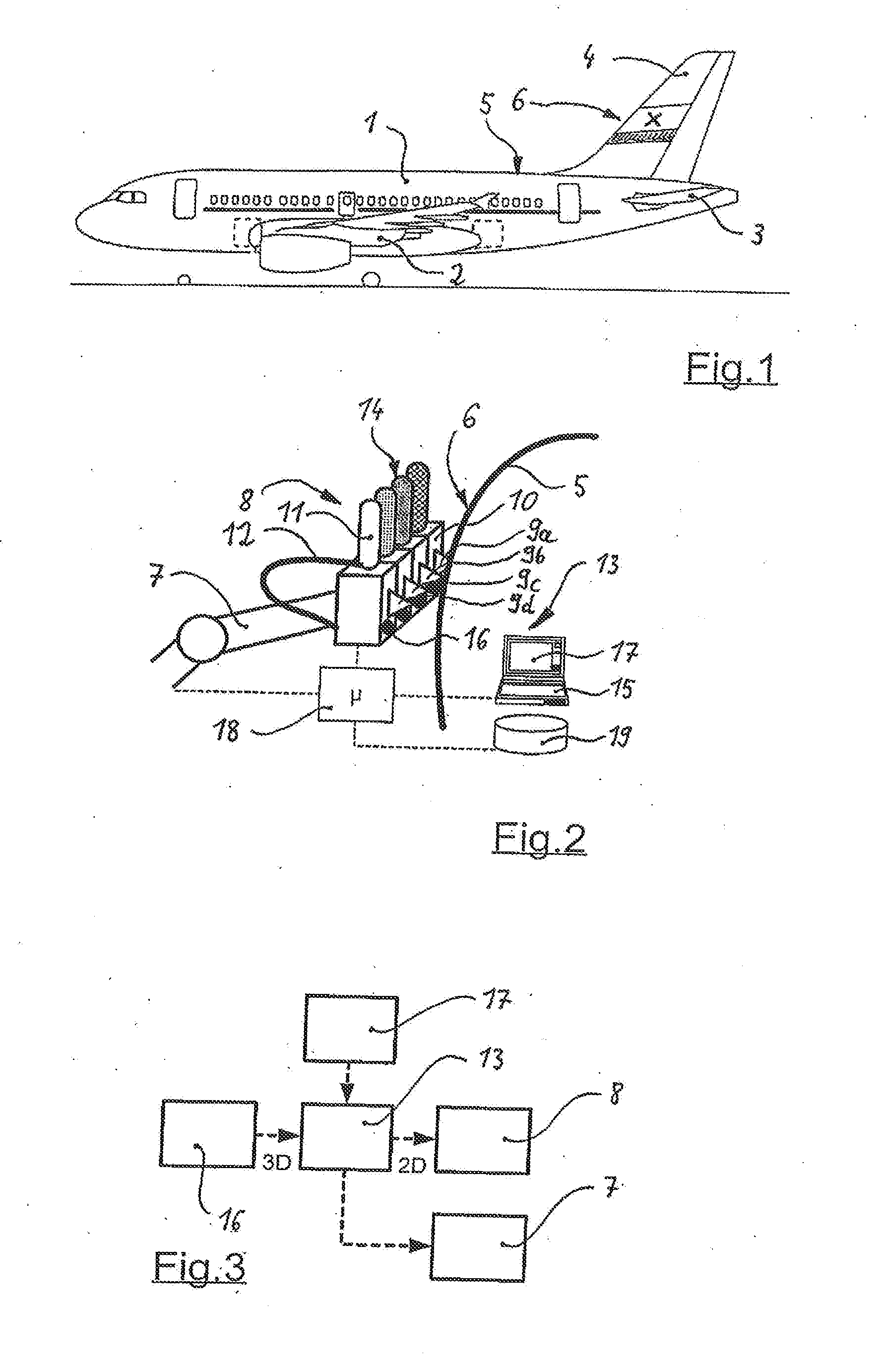
[0022]According to FIG. 1, an aircraft—that is realized in the form of a passenger aircraft-features a fuselage 1, on which a wing 2 with engines is laterally arranged. The rear side of the fuselage 1 features an elevator unit 3, as well as a rudder unit 4 that protrudes upward from the fuselage 1 by a significant distance.

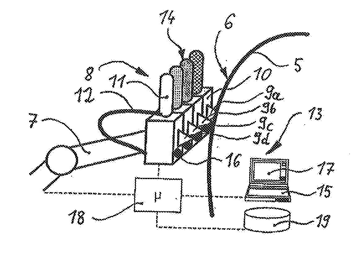
[0023]In this exemplary embodiment, the outer surface 5 of the rudder unit 4 is provided with a photo-realistic picture motif 6 that consists of many color gradations. The outer surface 5 of the rudder unit 4 is essentially curved in one plane, onto which the picture motif 6 is automatically applied in the form of PUR aircraft paint with the aid of the device described below.

[0024]According to FIG. 2, the device for painting the—only sectionally illustrated—outer surface 5 essentially consists of a spatially adjustable positioning device 7, on which a paint applicator 8 is arranged, wherein the positioning device 7 and the paint applicator 8 are driven along the c...


PUM


Abstract

A device for painting a curved outer surface of an aircraft includes a paint applicator having a plurality of spray painting heads each assigned to one of a plurality of different base color supply units containing one of polyurethane aircraft paint and ink. The device further includes a spatially adjustable positioning device configured to move the paint applicator relative to the curved outer surface and at least one sensor device configured to determine a three-dimensional geometry of the curved outer surface. The device also includes a control unit configured to coordinate a movement of the positioning device with a paint output of the paint applicator, wherein the control unit is configured to alternately activate each of the plurality of spray painting heads so as to produce a picture motif so as to derive a two-dimensional driving geometry based on the three-dimensional geometry.

Description

CROSS-REFERENCE TO RELATED APPLICATIONS[0001]This application is a divisional of U.S. patent application Ser. No. 12 / 781,129, filed on May 17, 2010, which claims priority from both the German Patent Application No. DE 10 2009 021 608.1, filed on May 15, 2009 and the U.S. Provisional Application No. 61 / 178,632, filed on May 15, 2009, the disclosures of which are incorporated herein by reference.[0002]The present invention pertains to a device and a method for painting a preferably curved outer surface of an aircraft, comprising a spatially adjustable positioning device for moving a paint applicator relative to the curved outer surface in accordance with a control unit for coordinating the movement of the positioning device with the paint output of the paint applicator in order to produce a picture motif.[0003]The field of application of the invention predominantly concerns the construction of aircraft, namely aircraft for transporting passengers and cargo. In addition, it would also ...

Claims


Application Information

Patent Timeline
Patent Type & Authority Applications(United States)
IPC IPC(8): B05B13/04B05D1/02B05B7/24B05B12/14B05B12/12
CPCB05B13/0431B05B12/1409B05D1/02B05B13/0452B05B7/2472B05B12/122B05B1/14B05B12/00B05B12/124B05B12/1472B25J11/0075B41J3/4073B05B12/02B05B12/10B05B13/0457B05B13/0468B05B13/0473B05C5/0208B05C5/0216B41J25/308G05B2219/45013
Inventor BAUSEN, DIRKKUHLENSCHMIDT, BIRGITHAUSMANN, KARLBENSE, ROLFSIEWERT, REBECCALAHIDJANIAN, DANIEL
Owner AIRBUS OPERATIONS GMBH
Learn More