Protective member

a protective member and member technology, applied in the field of protective members, can solve the problems of loss of consciousness and hearing, injury to axons, confusion, nausea, etc., and achieve the effect of reducing the amount of linear and rotational acceleration

Inactive Publication Date: 2016-12-22
PHIPPS EMERSON SPALDING +1
View PDF3 Cites 21 Cited by
  • Summary
  • Abstract
  • Description
  • Claims
  • Application Information

AI Technical Summary

Benefits of technology

[0011]A protective member includes an outer layer and an inner layer interconnected by multiple connectors, such as extension springs, under tension along their longitudinal axis. The connectors absorb energy from an impact force by resisting further tension along their longitudinal axis, can elongate along their longitudinal axis and allow the layers to move relative to each other. The protective member reduces the amount of linear and rotational acceleration experienced by the protected area, item or individual. The protective member can be used in numerous applications and environments.

Problems solved by technology

Immediate effects can include dizziness, confusion, nausea, loss of consciousness and difficulty seeing and hearing.
Acceleration of the brain can apparently cause injury to axons.

Method used


Image

  • Protective member
  • Protective member
  • Protective member

Examples


Embodiment Construction

[0031]The following detailed description of the preferred embodiments should be read in view of the FIGS. in which the same reference numerals are used to refer to the same or corresponding components of the novel protective helmet of the invention.

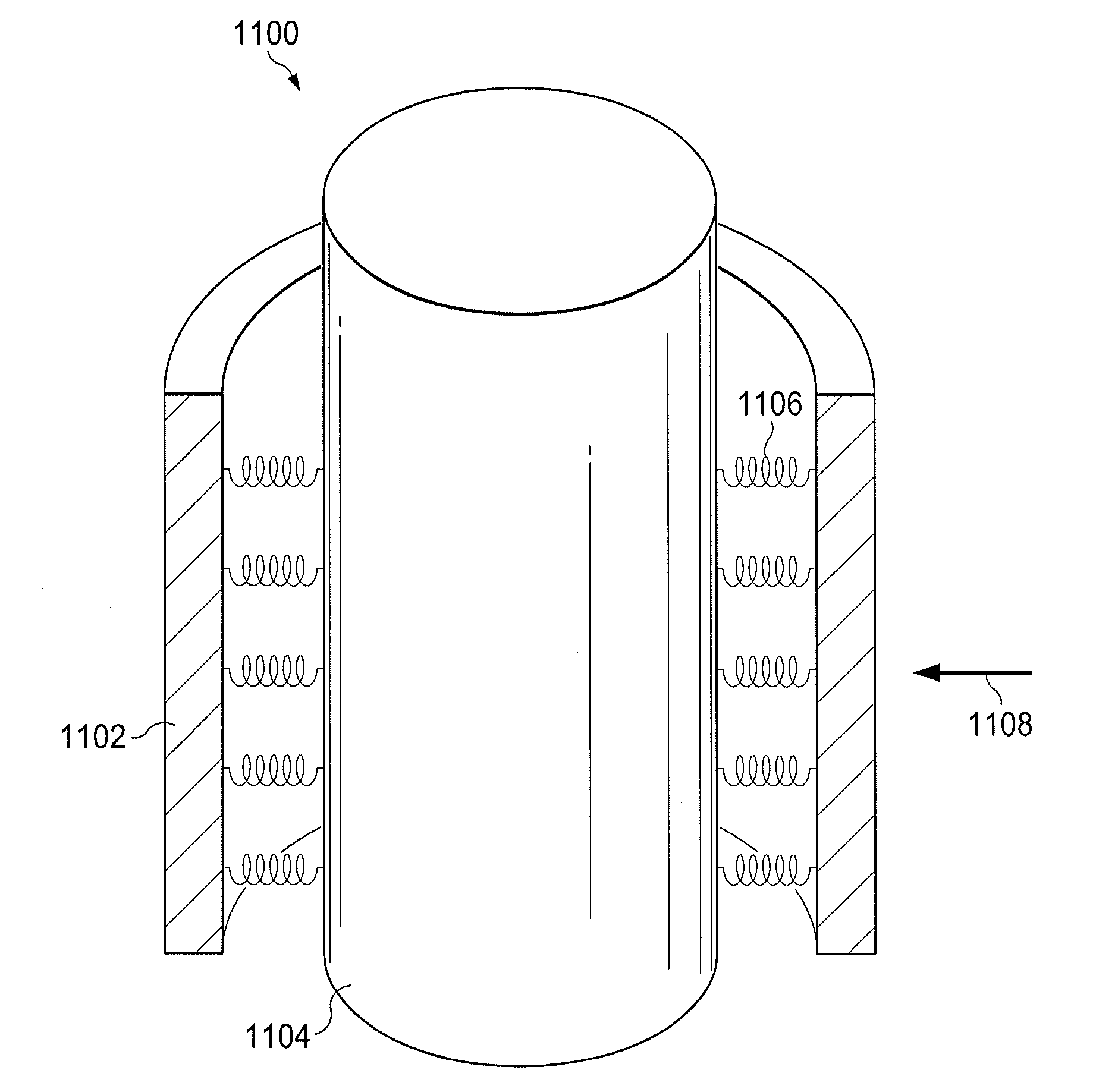
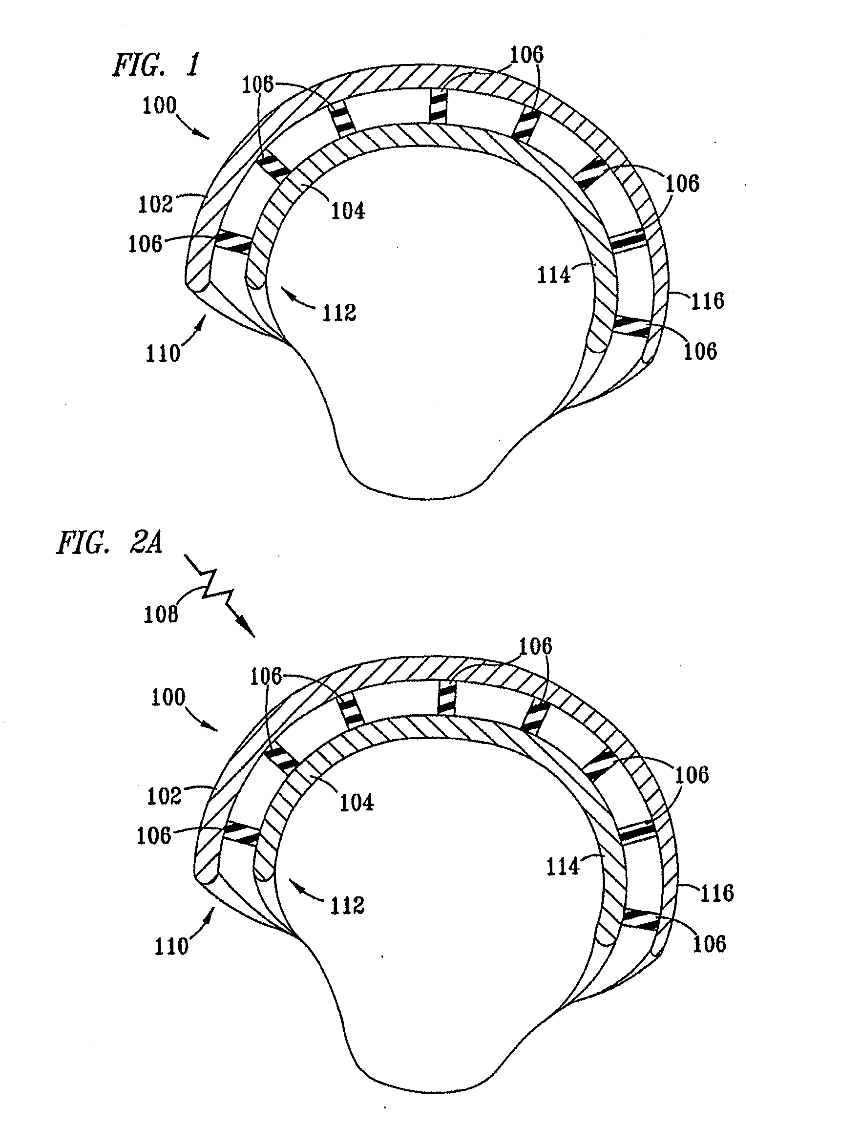
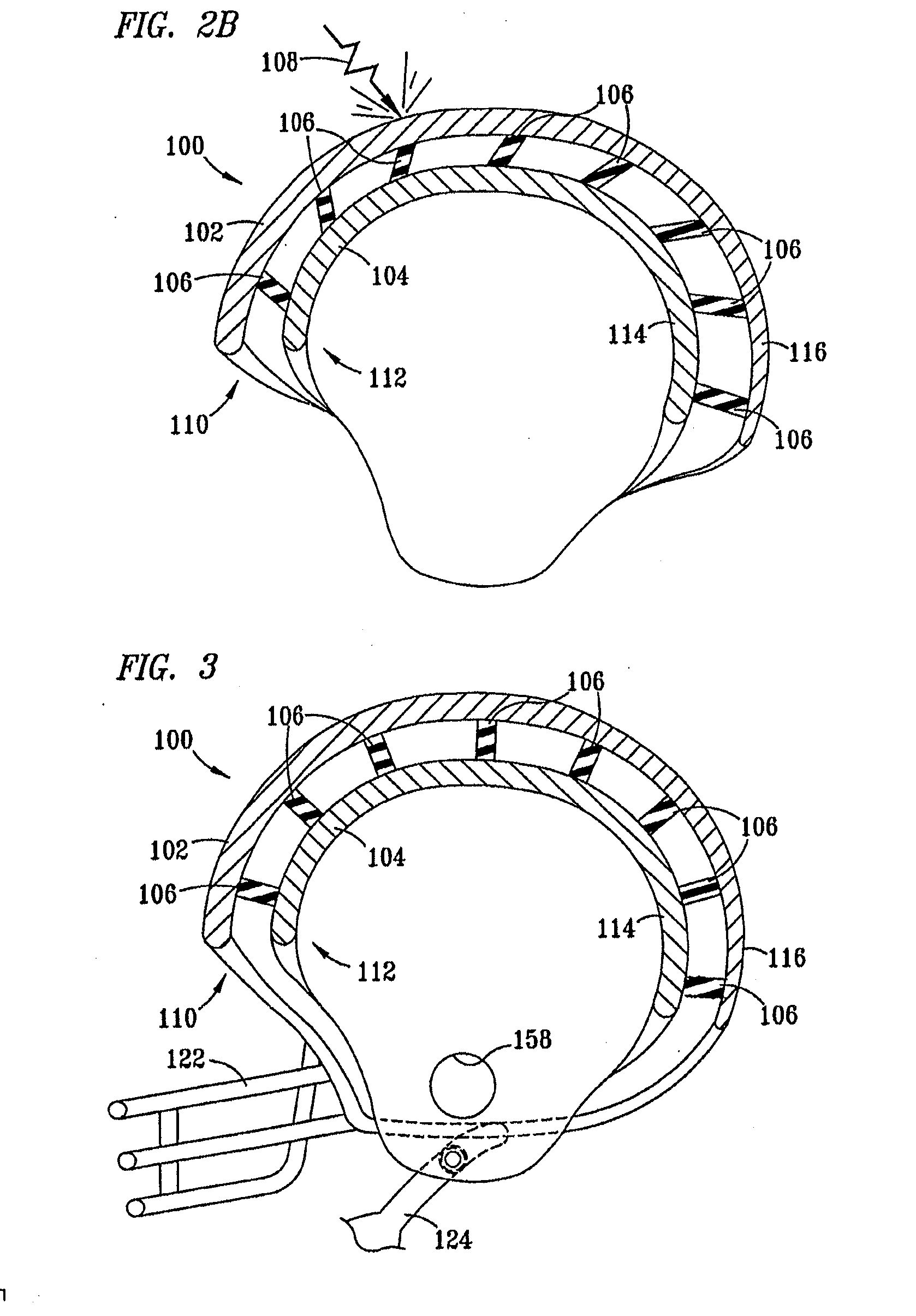
[0032]As shown in FIG. 1, the novel protective helmet 100, includes an outer layer 102, an inner layer 104 and multiple connectors 106. The multiple connectors 106 are disposed between and connect inner layer 104 to outer layer 102. Connectors 106 preferably connect outer layer 102 to inner layer 104 such that each connector 106 is under tension along its longitudinal axis. As understood by those skilled in the art, the term “tension” means the opposite of compression. Being “under tension” therefore means being subject to a force that tends to stretch the connector. Thus, the tension force on the connectors 106 is a force tending to stretch or elongate the connectors 106. The connectors 106 are not fully stretched in their initial or at ...


PUM


Abstract

A protective member includes outer and inner layers interconnected by multiple connectors under tension along their longitudinal axis. The connectors absorb energy from an impact force by resisting further tension along their longitudinal axis, can elongate along their longitudinal axis and allow the layers to move relative to each other. The protective member can be used in numerous applications and environments, including for participants in sports, in applications including bumpers, passenger cabins, car seats, beds, torso protection, ships, gloves, footwear and items.

Description

RELATED APPLICATIONS[0001]This application is a continuation of an application filed on Jul. 11, 2014, U.S. application Ser. No. 14 / 329,427 (“the '427 application”). This application claims the benefit of the priority date of the '427 application. The '427 application is a continuation-in-part of an application filed on Mar. 11, 2013, U.S. application Ser. No. 13 / 792,812 (“the '812 application”). This application also claims the benefit of the priority date of the '812 application. The '812 application is a continuation-in-part of U.S. application Ser. No. 13 / 227,901 (“the '901 application”), filed on Sep. 8, 2011. This application also claims the priority date of the '901 application. The '427 application, the '812 application and the '901 application are hereby incorporated by reference.TECHNICAL FIELD OF THE INVENTION[0002]The present invention generally relates to protective members useful as helmets and other protective members comprising connectors such as extension springs th...

Claims


Application Information

Patent Timeline
Patent Type & Authority Applications(United States)
IPC IPC(8): F16F3/087A41D13/05A41D13/08A42B3/12F16F3/04A41D19/015A43B13/18B60R19/18B63B59/02A42B3/06A41D13/015
CPCF16F3/0873F16F2236/045A41D13/0518A41D13/08A42B3/127A41D13/015A41D13/0543A41D19/01523A43B13/186A41D13/0525B60R19/18B63B59/02F16F3/04B60R2019/186F16F2230/0023A42B3/064A47C23/043A47C27/06B60N2/42B60N2/4221B60N2/4228B60N2/4235B60N2/4242B60N2/42736B60R19/28B60R2019/1893A43B7/32A43B13/181A43B23/0235A43B23/028A41D31/285F16F3/0876G01L5/0052
Inventor PHIPPS, EMERSON SPALDINGPHIPPS, CHARLES EDWARD
Owner PHIPPS EMERSON SPALDING
Why Eureka
Try Eureka