Composite cable assembly with neutral buoyancy
a composite cable and buoyancy technology, applied in the field of elongated elements, can solve the problems of high latency, high cost, and bulky composite cable, and achieve the effect of slow sinking
- Summary
- Abstract
- Description
- Claims
- Application Information
AI Technical Summary
Benefits of technology
Problems solved by technology
Method used
Image
Examples
first embodiment
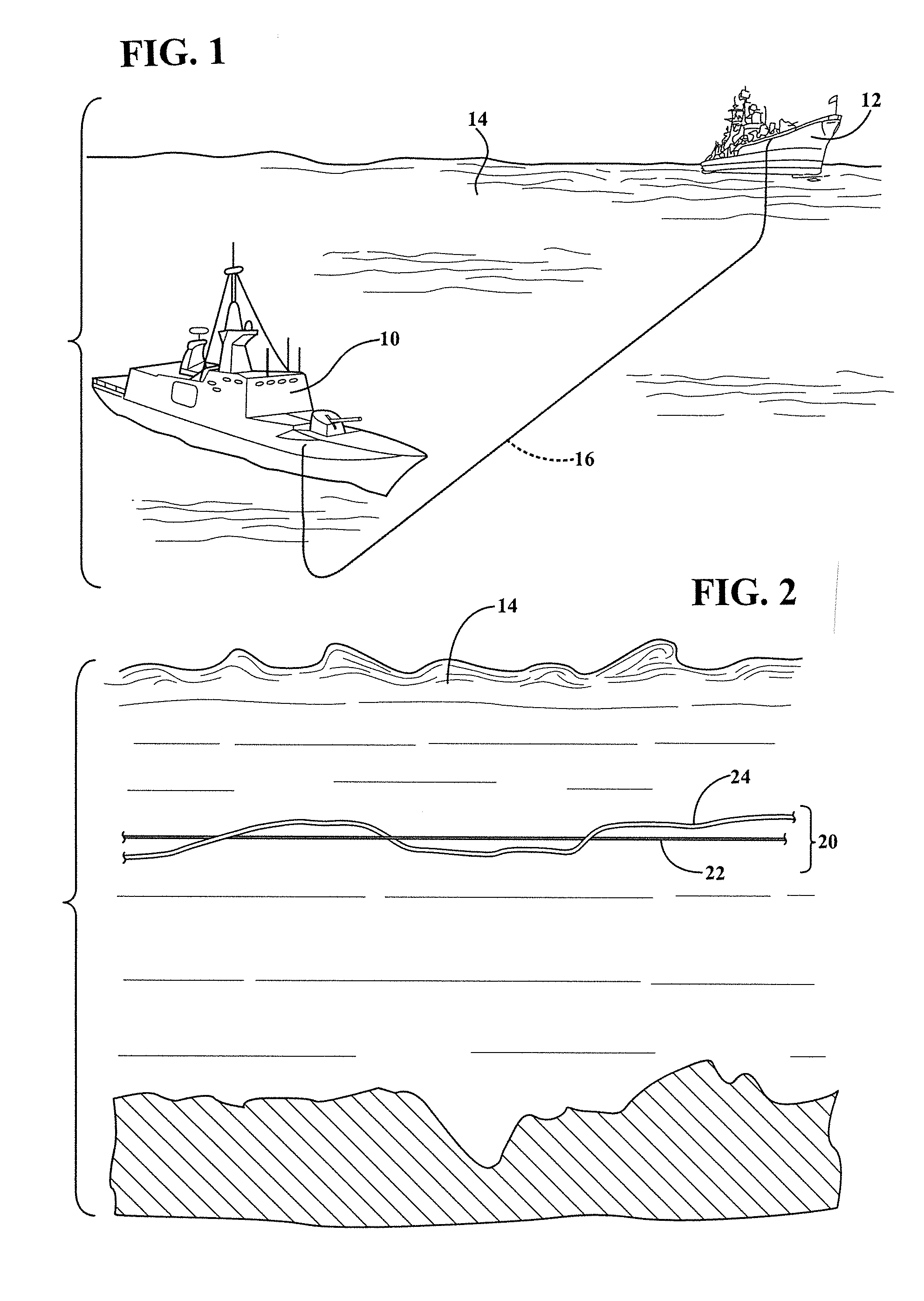
[0049]FIG. 2 illustrates the present invention wherein a composite cable assembly 20 is formed by interconnecting an elongated element 22 with an elongated supplemental filament 24. In the illustrated embodiment, the filament 24 is loosely coiled around the elongated element 22. In one example, the element 22 is an optical fiber having a negative buoyancy in the fluid environment 14. The supplemental filament 24 may be any elongated element with a positive buoyancy such that the combination of the optical fiber 22 and filament 24 create a composite assembly with a composite buoyancy that is generally neutral in the fluid environment 14.
second embodiment
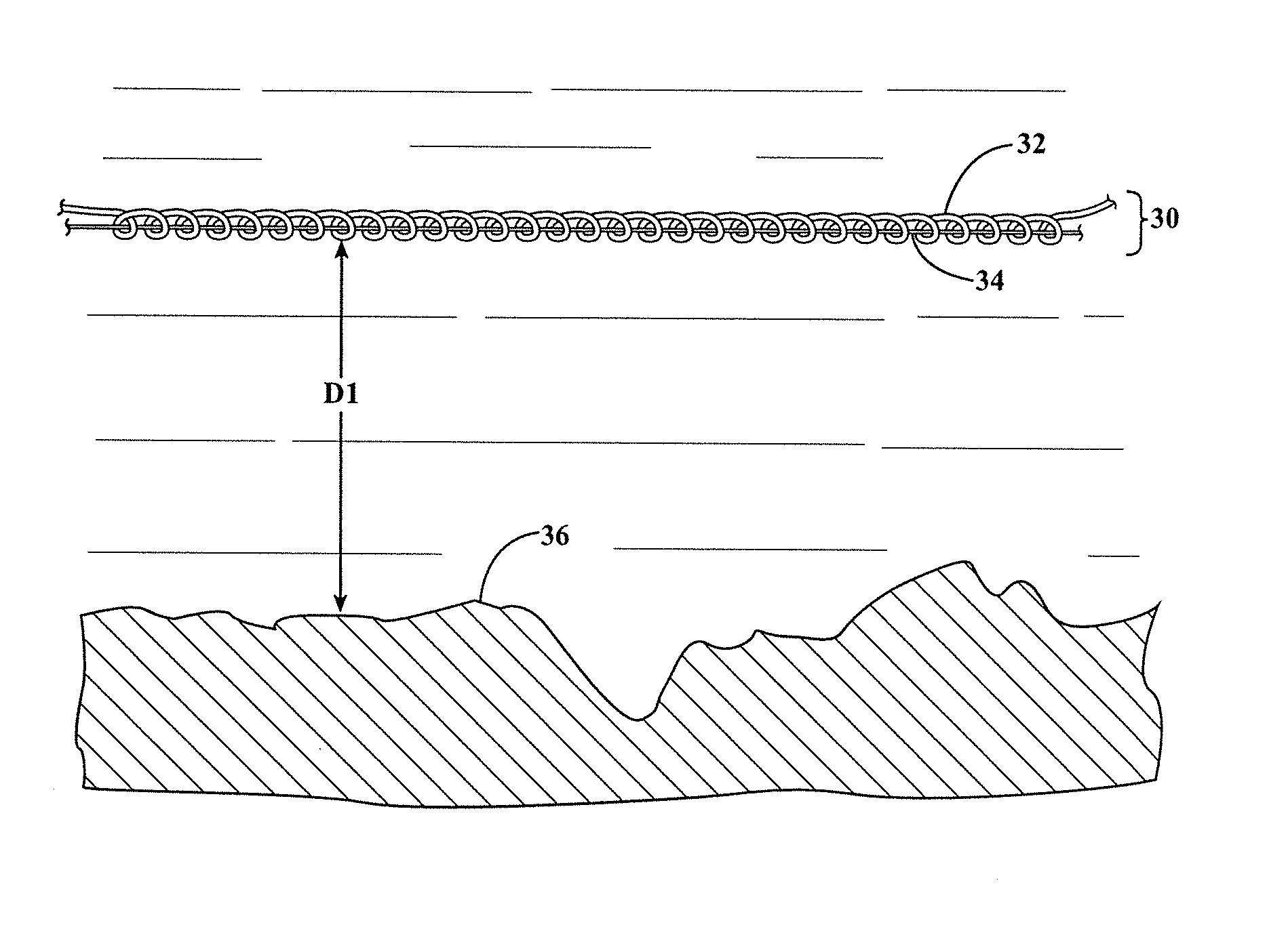
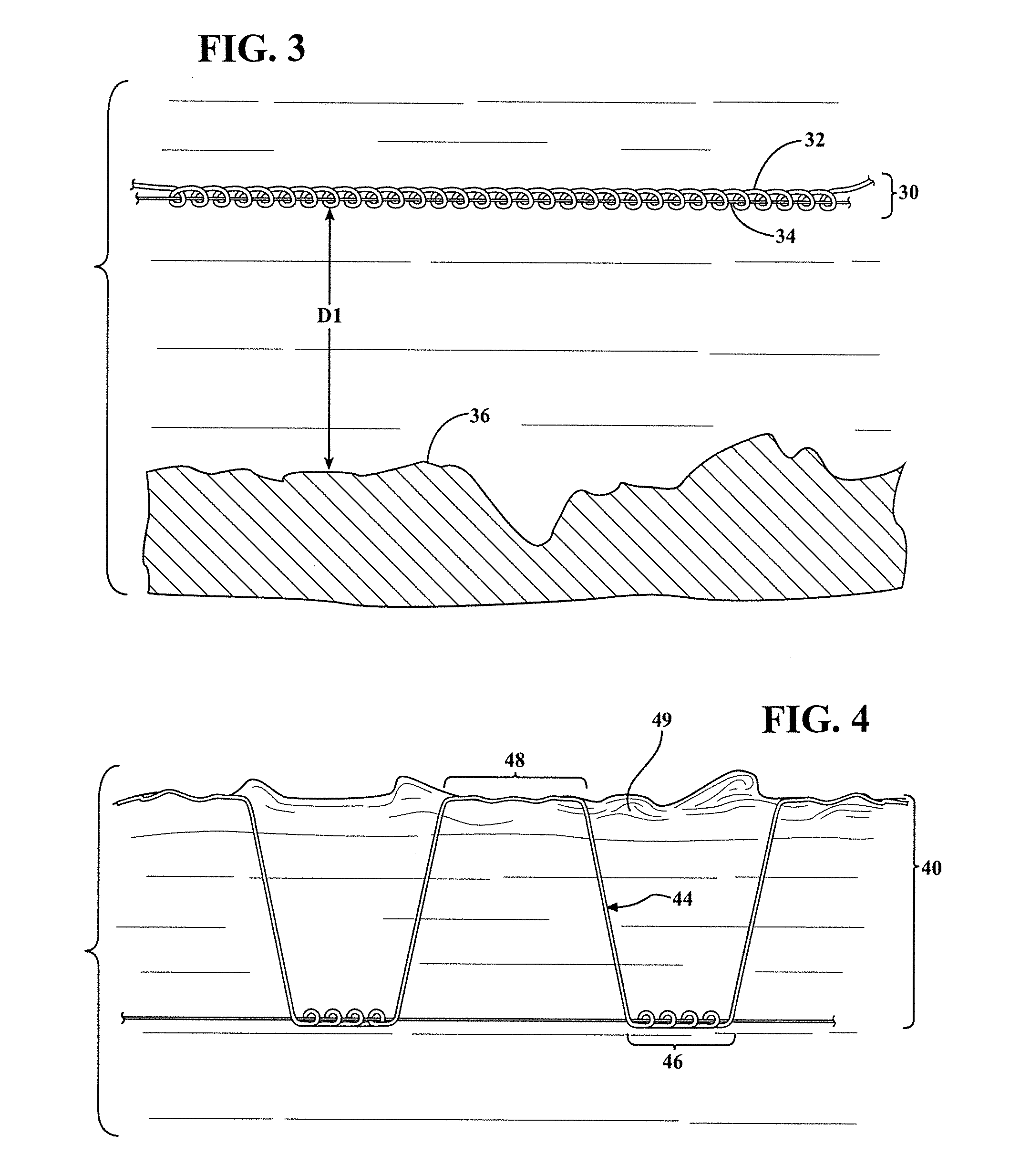
[0050]FIG. 3 illustrates the present invention in which a composite assembly 30 includes an elongated element 32 and a supplemental filament 34. As shown, the supplemental filament 34 is coiled around the elongated element 32 with significantly more coils per unit length than in FIG. 2. As will be clear to those with skill in the art, the number of coils of filament per unit length of elongated element will depend on the relevant buoyancies of the element and filament as well as other factors. The assembly 30 is shown suspended in the fluid environment at a distance D1 above a lower boundary 36 of the fluid environment. While FIGS. 2 and 3 illustrate the elongated element and supplemental filament being interconnected by coiling the supplemental filament around the elongated element, numerous other approaches to connection may be used. For example, the elongated element may be partially coiled around the filament, the filament and elongated element may be glued together or the eleme...
third embodiment
[0051]Referring now to FIG. 4, the present invention is shown. Again, the composite assembly 40 includes an elongated element 42 and a supplemental filament 44. However, this embodiment differs in that the supplemental filament 44 includes connected portions 46 that are connected to the elongated element 42 and detached portions 48 that are not connected to the elongated element 42 such that the detached portions 48 may extend away from the elongated element 42 when in the fluid environment. In the illustrated embodiment, the filament 44 is continuous such that the connected portions 46 and detached portions 48 are part of the same elongated element. In the illustrated embodiment, part of the detached portion 48 extends to upper boundary 49 of the fluid environment and floats thereon. This may be referred to as a floating portion, and is a part of the detached portion. A transition portion extends between the floating portion and the connected portion 46 by extending downwardly in t...
PUM
 Abstract
Description
Claims
Application Information
 - R&D
- Intellectual Property
- Life Sciences
- Materials
- Tech Scout
- Unparalleled Data Quality
- Higher Quality Content
- 60% Fewer Hallucinations
Browse by: Latest US Patents, China's latest patents, Technical Efficacy Thesaurus, Application Domain, Technology Topic, Popular Technical Reports.
© 2025 PatSnap. All rights reserved.Legal|Privacy policy|Modern Slavery Act Transparency Statement|Sitemap|About US| Contact US: help@patsnap.com


