Method and system for monitoring of a physical quantity related to a particulate mass in at least one exhaust pipe

a technology of at least one exhaust pipe and a physical quantity, applied in the direction of exhaust treatment electric control, machines/engines, mechanical equipment, etc., can solve the problems of low reliability, low cost, and uneven use of soot sensors in exhaust pipes, and achieve accurate and reliable monitoring of particulate mass m, cost effective and reliable

Active Publication Date: 2017-02-02
SCANIA CV AB
View PDF4 Cites 8 Cited by
  • Summary
  • Abstract
  • Description
  • Claims
  • Application Information

AI Technical Summary

Benefits of technology

[0017]Through the use of the present invention, a correlation between the pressure difference reduction Δ over at least one or several particulate filters and the particulate mass M downstream of these one or several particulate filters may thus be obtained and used to determine a level of the particulate mass M, emitted into the atmosphere from the vehicle. Accordingly, an accurate and reliable monitoring of the particulate mass M emitted into the atmosphere may be obtained.
[0018]With the use of the present invention, the requirement for the resistive and / or electrostatic soot sensors in the at least one exhaust pipe, which previously has been used in some vehicles to determine the particulate mass in the at least one exhaust pipe, is thus eliminated. The present invention provides a cost effective and reliable solution to the above mentioned problem for prior art systems.

Problems solved by technology

However, the use of soot sensors in exhaust pipes has been shown to have several disadvantages.
The resistive sensors, electrostatic sensors and other types of sensors, in use today as soot sensors, are expensive.
Additionally, these sensors have been developed relatively recently and have a low, and sometimes also uneven, reliability.
Exhaust pipes are a problematic environment for sensors, since the exhausts typically comprise particles that hamper measurements and even soil the sensors.
Accordingly, prior art solutions have relied upon measurements made sensors that often were soiled, in an environment where it may be difficult to discern the occurrence of some particles.
Additionally, these sensors often need to be replaced, or cleaned, because of the soiling, which means that the use of the sensors becomes costly due to material and labor costs, and because the vehicle must be taken out of service.

Method used


Image

  • Method and system for monitoring of a physical quantity related to a particulate mass in at least one exhaust pipe
  • Method and system for monitoring of a physical quantity related to a particulate mass in at least one exhaust pipe
  • Method and system for monitoring of a physical quantity related to a particulate mass in at least one exhaust pipe

Examples


Embodiment Construction

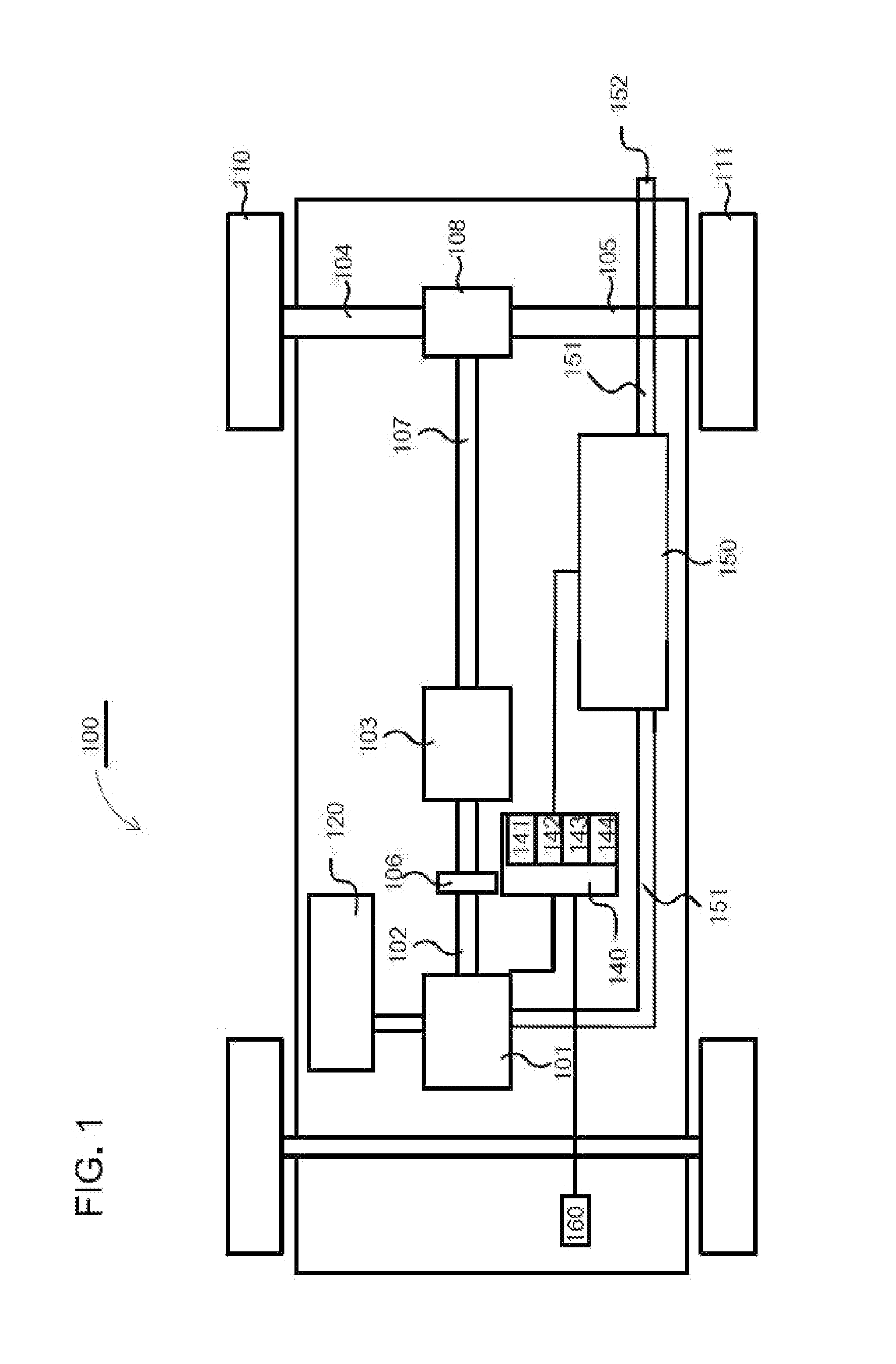
[0033]FIG. 1 schematically shows an example vehicle 100, comprising an exhaust treatment system 150, whereat the vehicle may comprise a system according to the present invention, which is described in more detail below. The vehicle has a powertrain comprising one combustion engine 101, which in a customary manner, via an output shaft 102 on the combustion engine 101, usually via a flywheel, is connected to an a gearbox 103 via a clutch 106. The vehicle's powertrain may also be of another type, such as of a type with a conventional automatic gearbox, of a type with a hybrid powertrain, of a type comprising more than one engine, etc.

[0034]An output shaft 107 from the gearbox 103 drives the wheels 110, 111 via a final drive 108, e.g. a customary differential, and the drive shafts 104, 105 connected to said final drive 108.

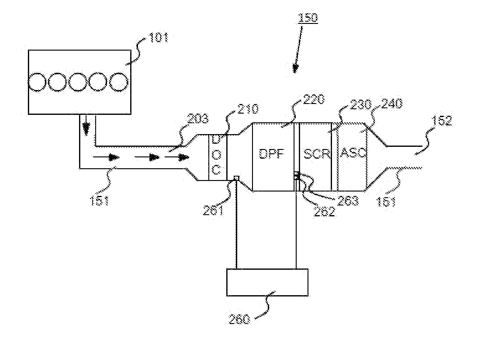
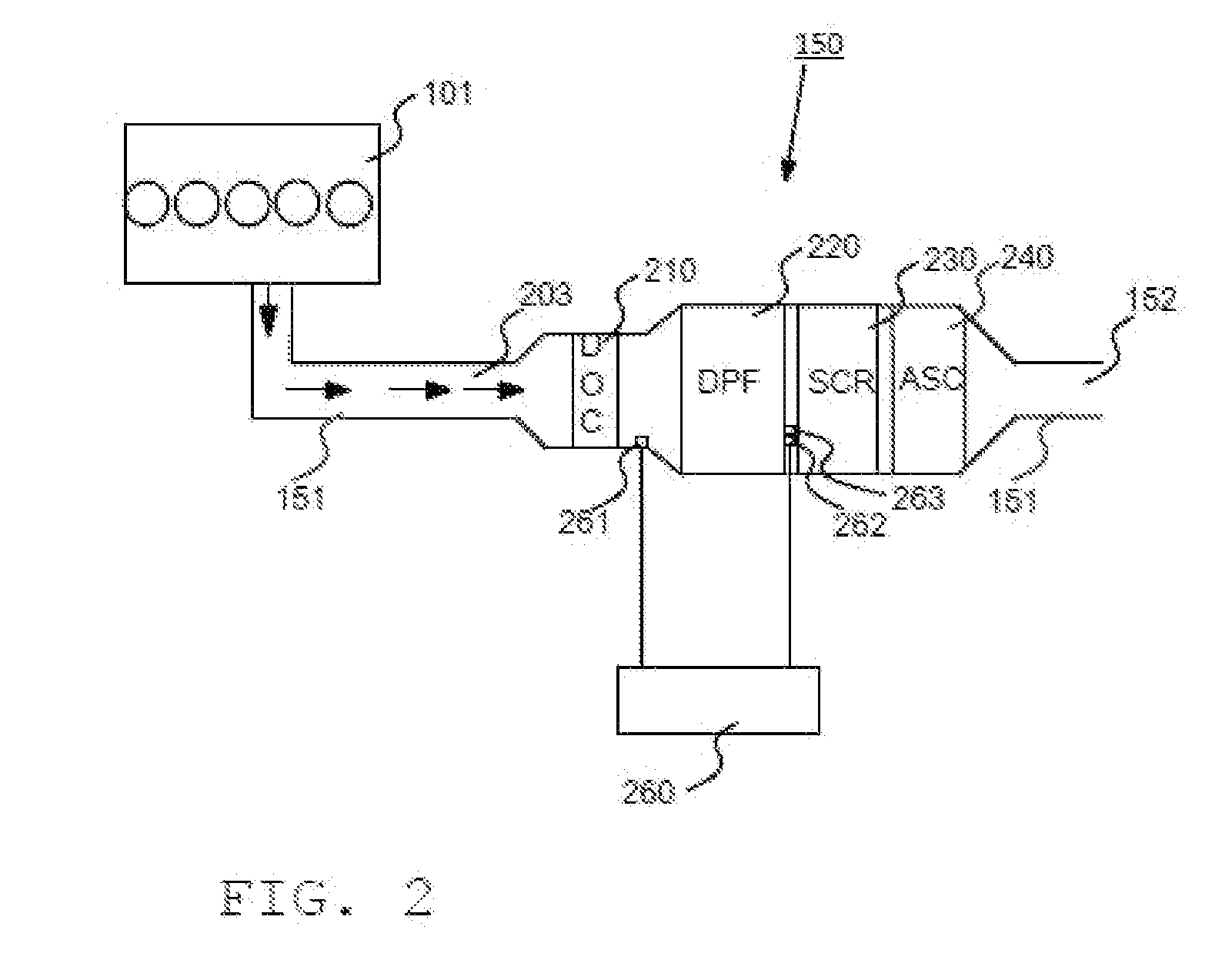
[0035]The vehicle 100 also comprises the above mentioned exhaust treatment system / exhaust purification system 150 for treatment / purification of exhaust emissions resu...


PUM


Abstract

Methods and systems are provided to monitor a quantity relating to particulate mass M in at least one exhaust pipe arranged downstream of a combustion engine. A first determination device determines a reduction Δ of a pressure difference dP over at least one or several particulate filters, arranged downstream of the combustion engine. This reduction Δ is related to a pressure difference dPref over one or more corresponding reference particulate filters. A second determination device determines a quantity related to the particulate mass M, based on the determined reduction Δ of the pressure difference dP and a predetermined correlation between the reduction Δ and the quantity related to the particulate mass M, so that use of soot sensors in the exhaust pipe may be avoided. A comparison device compares the quantity with a defined threshold value Mth and a providing device provides indications related to the comparison.

Description

CROSS-REFERENCE TO RELATED APPLICATION(S)[0001]This application is a national stage application (filed under 35 §U.S.C. 371) of PCT / 5E15 / 050499, filed May 6, 2015 of the same title, which, in turn claims priority to Swedish Application No. 1450544-0, filed May 8, 2014 of the same title; the contents of each of which are hereby incorporated by reference.FIELD OF THE INVENTION[0002]The present invention relates to a method, system, and computer program product for monitoring of at least one quantity in relation to a particulate mass in at least one exhaust pipe arranged downstream of at least one combustion engine.BACKGROUND OF THE INVENTION[0003]The following background description constitutes a description of the background to the present invention, and thus need not necessarily constitute prior art.[0004]Engines, such as for example engines comprised in vehicles or ships, are usually equipped with an exhaust treatment system for purification of exhausts created during combustion in...

Claims


Application Information

Patent Timeline
Patent Type & Authority Applications(United States)
IPC IPC(8): F01N11/00F01N3/021
CPCF01N11/007F01N11/002F01N2560/05F01N2550/04F01N3/021F01N2900/06F01N9/002F01N11/00F01N2560/08F01N2900/0412F01N2900/1406F01N2900/1606F01N3/106F01N2570/18Y02T10/12Y02T10/40F01N13/18F01N2900/04F01N9/00
Inventor BOKELUND, BJORNERWE, KAROLIN
Owner SCANIA CV AB
Why Eureka
Try Eureka