
Methods and system for thermo-optic power monitoring

a technology of thermo-optic power monitoring and monitoring system, applied in the direction of optical radiation measurement, instruments, spectrometry/spectrophotometry/monochromators, etc., can solve the problems of increasing system complexity and cost, difficult to accurately monitor lighting devices, etc., and achieve accurate monitoring of lighting devices. , the effect of increasing radiation level

Active Publication Date: 2021-01-19
PHOSEON TECHNOLOGY INC
View PDF12 Cites 0 Cited by
  • Summary
  • Abstract
  • Description
  • Claims
  • Application Information

AI Technical Summary

Benefits of technology

The invention provides a way to accurately and reliably monitor the output of lighting devices, without being affected by external sources of light or radiation. This is achieved by using a beam-splitter or prism to obtain an unperturbed fractional measurement of the incident light, or by employing identical light sources with one of them spatially separated from the other and provided with an isolated environment. The ratio of light from multiple sources must remain constant over time and ambient conditions. This invention reduces costs and complexity of the radiation monitor and increases its reliability and accuracy as compared with conventional devices.

Problems solved by technology

Accurate monitoring of lighting devices can be difficult because of extraneous light or radiation from external sources, including light output from the lighting device that is retro-reflected back towards the lighting device.
Furthermore, paired light sources increases a system complexity and cost since multiple light sources are employed and monitored.

Method used


Image

  • Methods and system for thermo-optic power monitoring
  • Methods and system for thermo-optic power monitoring
  • Methods and system for thermo-optic power monitoring

Examples


Embodiment Construction

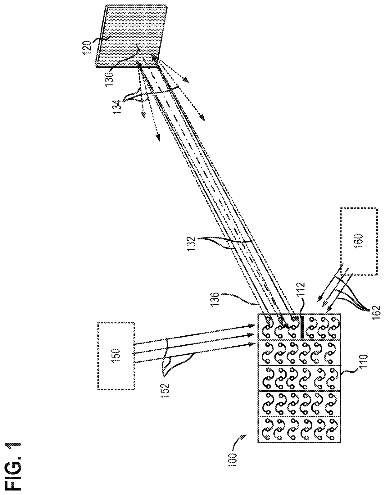
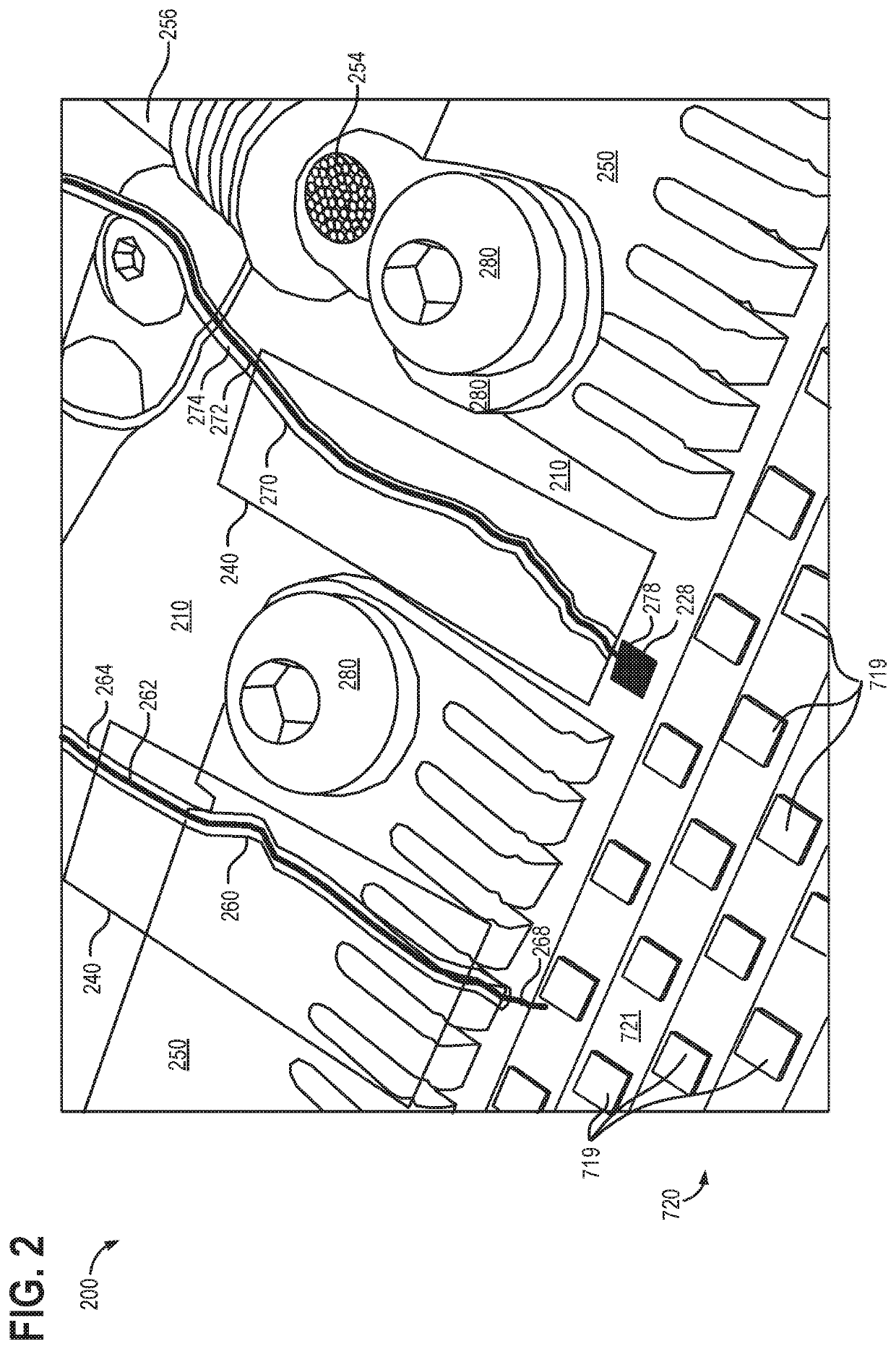
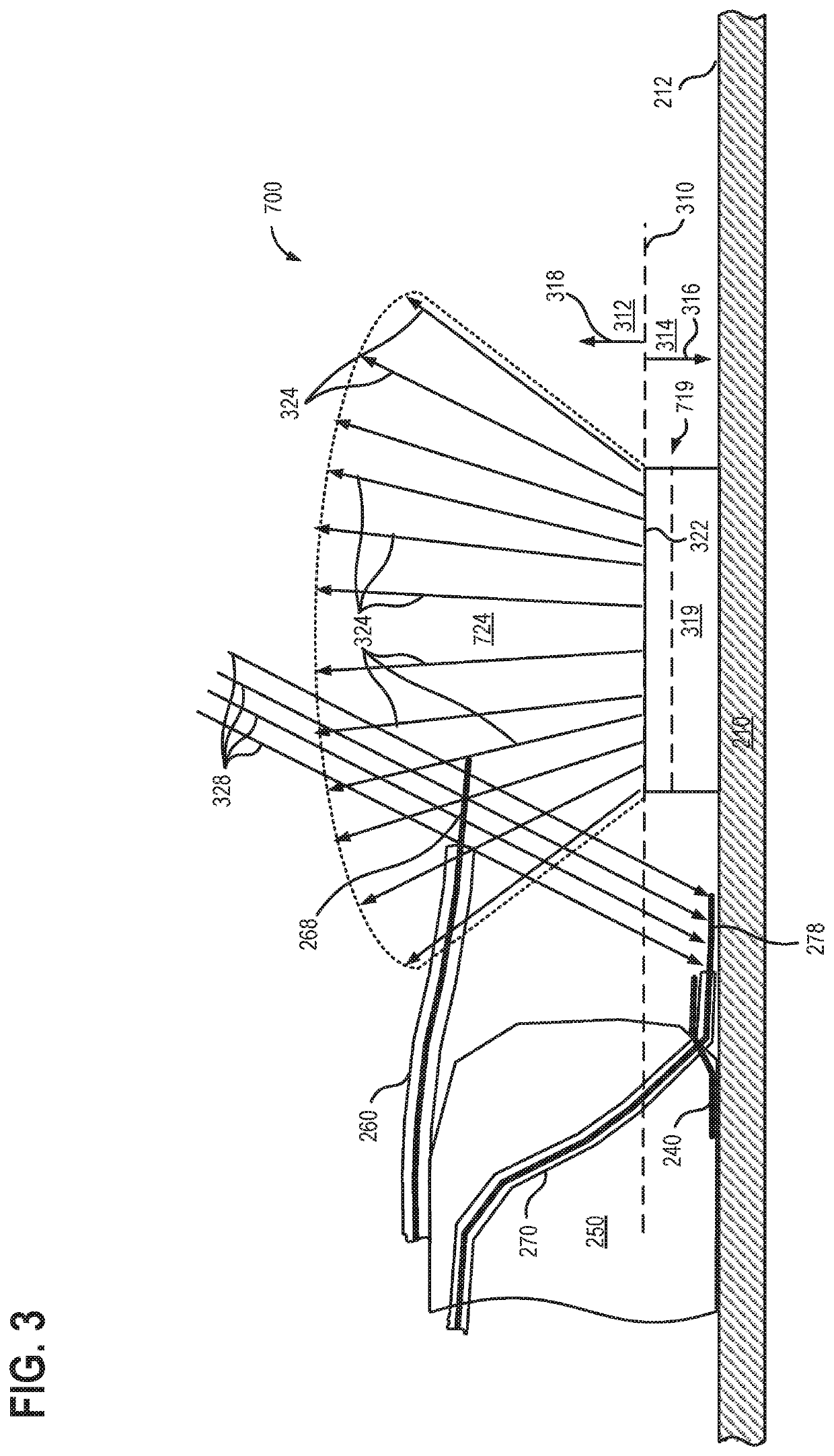
[0019]The present description relates to a radiation monitor, and methods and systems of radiation monitoring, which increase reliability and accuracy relative to conventional systems and methods by subtracting incident radiation from external sources, including retro-reflected radiation. FIG. 1 illustrates how retro-reflective surfaces and retro-reflected radiation can direct extraneous light back to a lighting device. A radiation monitor, such as the example apparatus shown in FIGS. 2-3, may remove retro-reflected radiation, as well as other radiation from external sources, from a measured output of a lighting device. A further example of a radiation monitor that may remove retro-reflected radiation and other radiation from external sources from a measured output of a lighting device is illustrated in FIGS. 4-6. The radiation monitor of FIGS. 4-6 may employ light capillaries, as illustrated in FIG. 12 and FIG. 13. FIG. 7 illustrates a system including a lighting device integrated ...


PUM


Abstract

A radiation monitor for a lighting device, and operating methods and systems therefor are provided. In one example, a radiation monitor may include a first sensor receiving radiation output directly from a light-emitting element of the lighting device and radiation output from external sources; and a second sensor receiving the radiation output from the external sources without receiving the radiation output directly from the light-emitting element of the lighting device. The radiation monitor may determine an intensity of the radiation output directly from the light-emitting element based on a difference in the output signals from the first sensor and the second sensor.

Description

CROSS REFERENCE TO RELATED APPLICATIONS[0001]The present application claims priority to U.S. Provisional Application No. 62 / 734,182 titled “METHODS AND SYSTEM FOR THERMO-OPTIC POWER MONITORING”, and filed on Sep. 20, 2018. The entire contents of the above-identified application are hereby incorporated by reference for all purposes.BACKGROUND AND SUMMARY[0002]Accurate monitoring of lighting devices can be difficult because of extraneous light or radiation from external sources, including light output from the lighting device that is retro-reflected back towards the lighting device. Owing to this incident radiation from external sources, photosensors in a conventional lighting device can indicate higher radiation levels than what is actually output from the lighting device. In cases where the lighting device emits polarized light, retro-reflected radiation incident at the lighting device can be mitigated by employing a beam-splitter or a prism, and obtaining an unperturbed fractional ...

Claims


Application Information

Patent Timeline
Patent Type & Authority Patents(United States)
IPC IPC(8): G01T1/16G01J3/10H05B45/22H05B45/40H05B44/00
CPCG01T1/16G01J3/10H05B45/22H05B45/40G01J2001/4247G01J1/4228G01J1/44G01J1/0422G01J5/12G01J1/4257H05B45/56
Inventor NORDSETH, GARYELIASON, GARTHNEUMANN, GORDONTILL, GARYMCKENZIE, GARY
Owner PHOSEON TECHNOLOGY INC
Learn More