

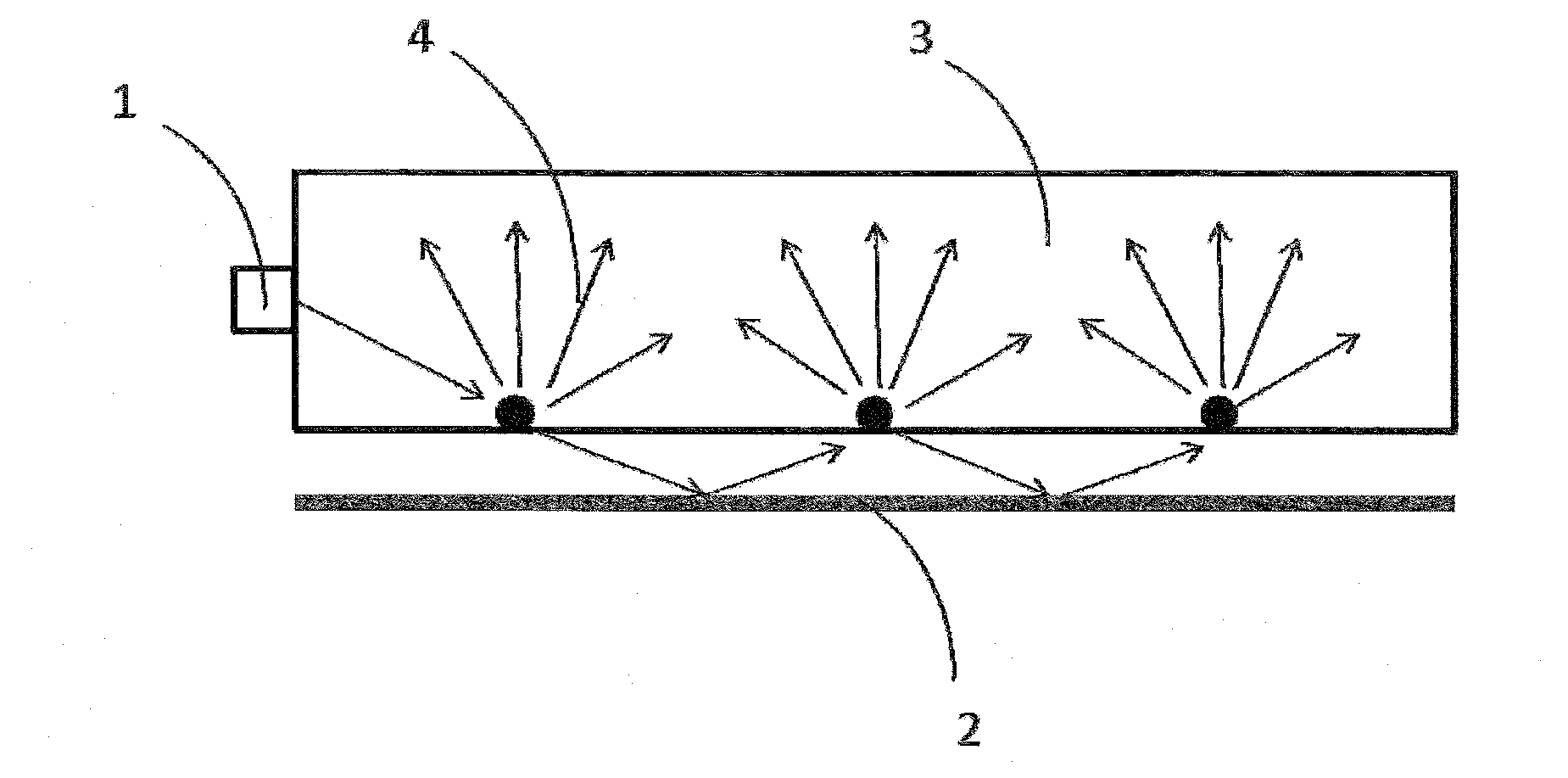
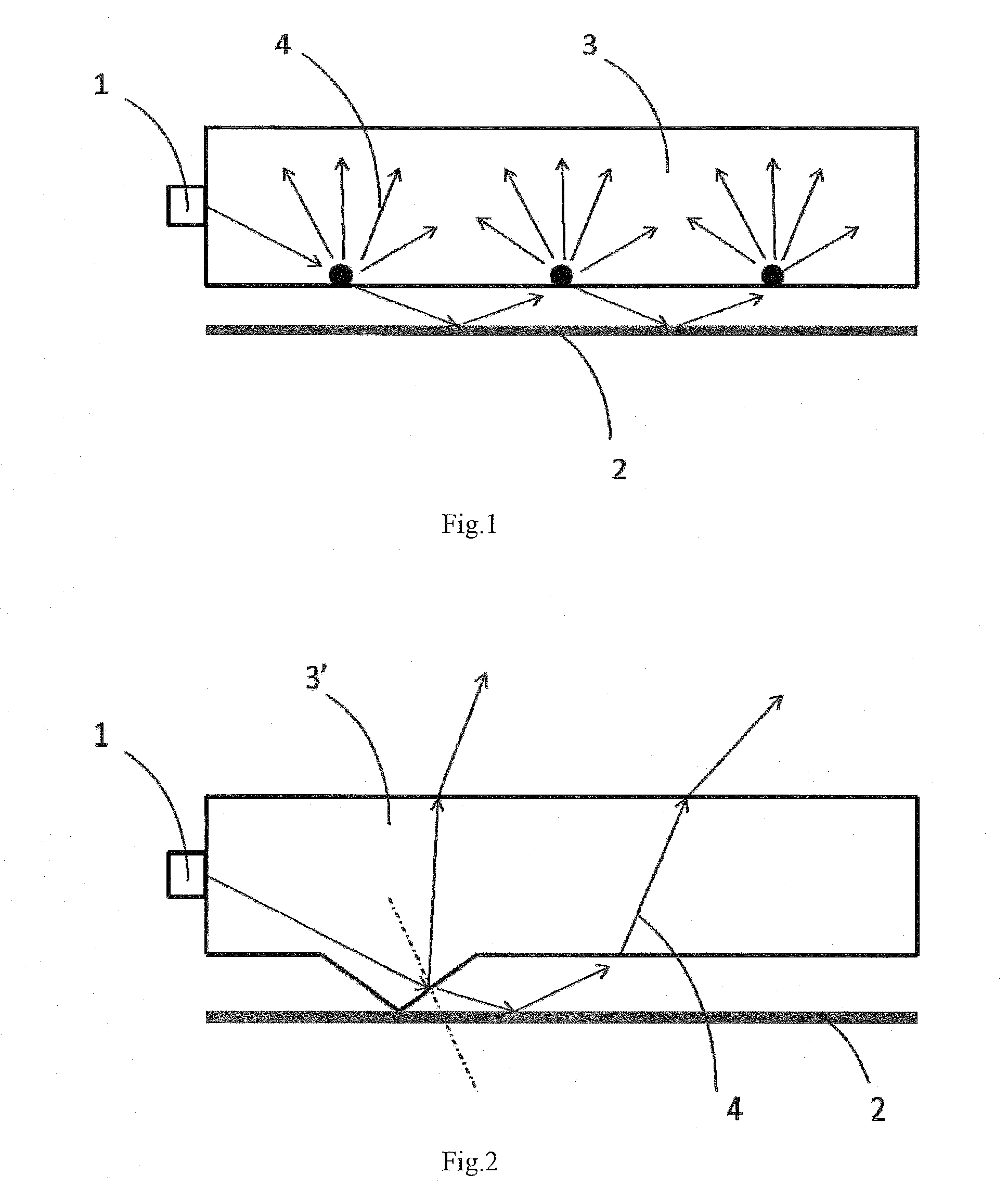
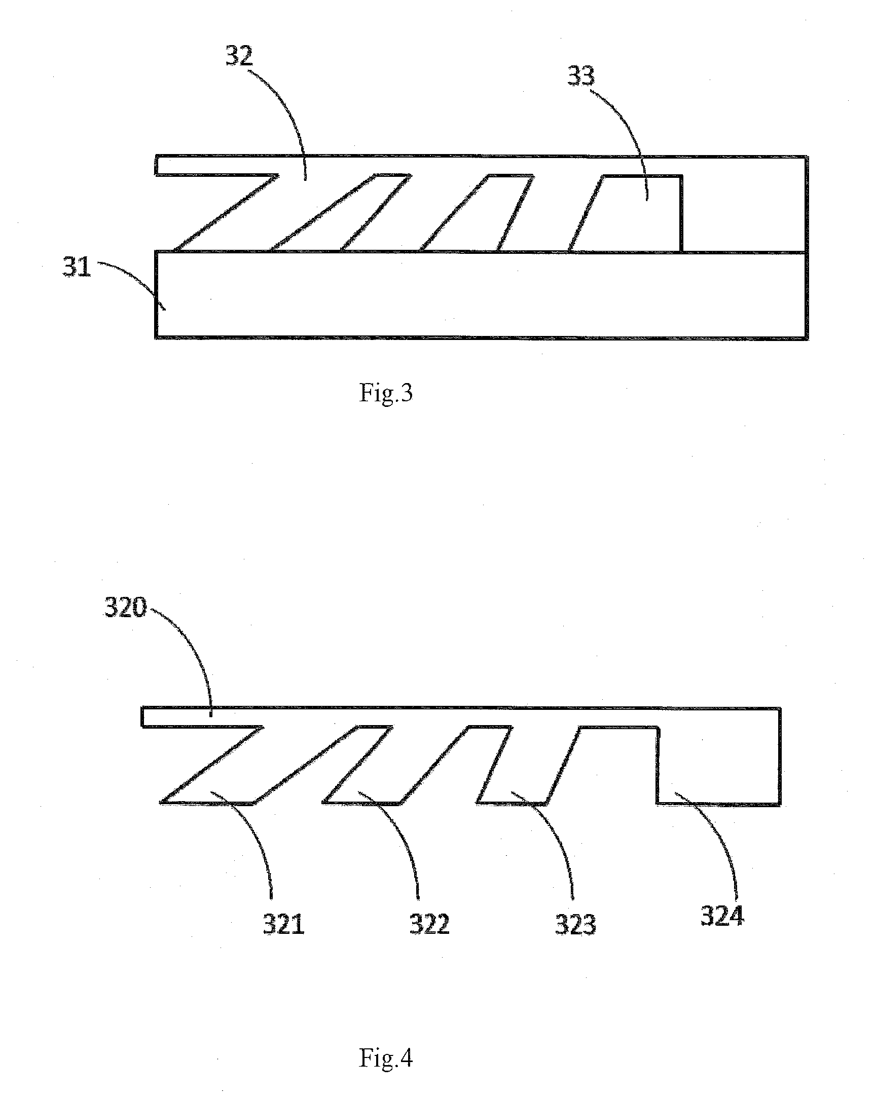
Light guide plate assembly and display apparatus
a technology of light guide plate and assembly, applied in the field of display technology, can solve the problems of affecting affecting the brightness of display, and the defect of low light distribution effect of edge-type backlight illumination, so as to increase the utilization ratio of light, increase the brightness of display, and increase the uniformity of backlight illumination
- Summary
- Abstract
- Description
- Claims
- Application Information
AI Technical Summary
Benefits of technology
Problems solved by technology
Method used
Image

Examples
Embodiment Construction
[0030]The objects, technical solutions and advantages of the present invention will become more clear and apparent by further explaining the present invention with reference to the embodiments and drawings below.
[0031]Before further explaining any embodiment in detail, it should be noted that the present invention is not limited to the configuration details provided in the following descriptions or illustrated in the following drawings and the component arrangements. The present invention may be implemented in other implementations or other forms.
[0032]The exemplary embodiments described in the detailed implementations and illustrated in the drawings are intended to teach the principle of the present invention, so as to enable those skilled in the art to implement and use the present invention. Thus, the exemplary embodiments should not be considered as limiting the scope of the present invention. It should be further noted that the drawings are merely illustrative and not drawn to ...
PUM
 Abstract
Description
Claims
Application Information