
Method and apparatus for hanging an object

a technology for hanging objects and hanging hardware, which is applied in the field of hanging objects, can solve the problems of frustration, needless damage to the wall, and the inability to remove and reattach the hanging hardwar

Active Publication Date: 2017-03-02
UNDER THE ROOF DECORATING
View PDF1 Cites 28 Cited by
  • Summary
  • Abstract
  • Description
  • Claims
  • Application Information

AI Technical Summary

Benefits of technology

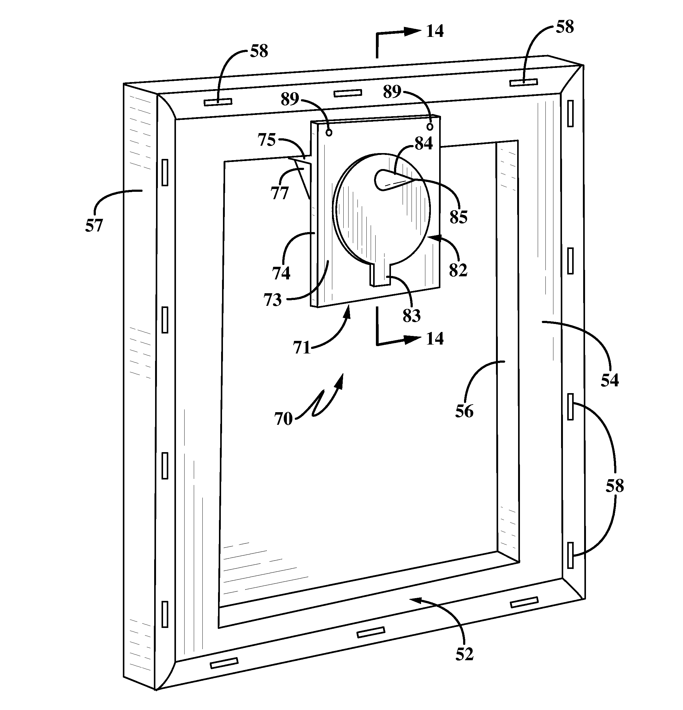
The invention provides an apparatus and method for mounting and hanging objects on a support structure using a bracket and fastener. The bracket has a marking device with a removable marking element for making a mark on the support structure after positioning the bracket on the object. The bracket can be easily secured to the object with the fastener and the marking element can be easily removed. The apparatus also includes a marking device for making a mark on the support structure at the proposed hanging location of the object. The invention simplifies the process of installing hardware on the support structure and makes it easier to suspend objects on the support structure.

Problems solved by technology

One of the common problems in hanging various types of objects on a supporting structure or wall, such as pictures, clocks, mirrors, and other decorations is the correct placement of the hanging hardware such as nails, screws, D-rings etc. on the wall so that the object is at the correct height and location after it is placed on the newly installed hanging hardware.
So often, once the hanging hardware is installed in the wall and the object placed thereon, the object is not at the location desired, resulting in removal and subsequent reattachment of the hanging hardware.
This results in frustration and needless damage to the wall.
There have been various devices developed for use in properly positioning the mounting hardware, such as various types of levels, laser devices, measuring devices, etc. which can be relatively expensive for only a single or several uses by the installer, and which once used requires subsequent storage for possible reuse in the future.

Method used


Image

  • Method and apparatus for hanging an object
  • Method and apparatus for hanging an object
  • Method and apparatus for hanging an object

Examples


Embodiment Construction

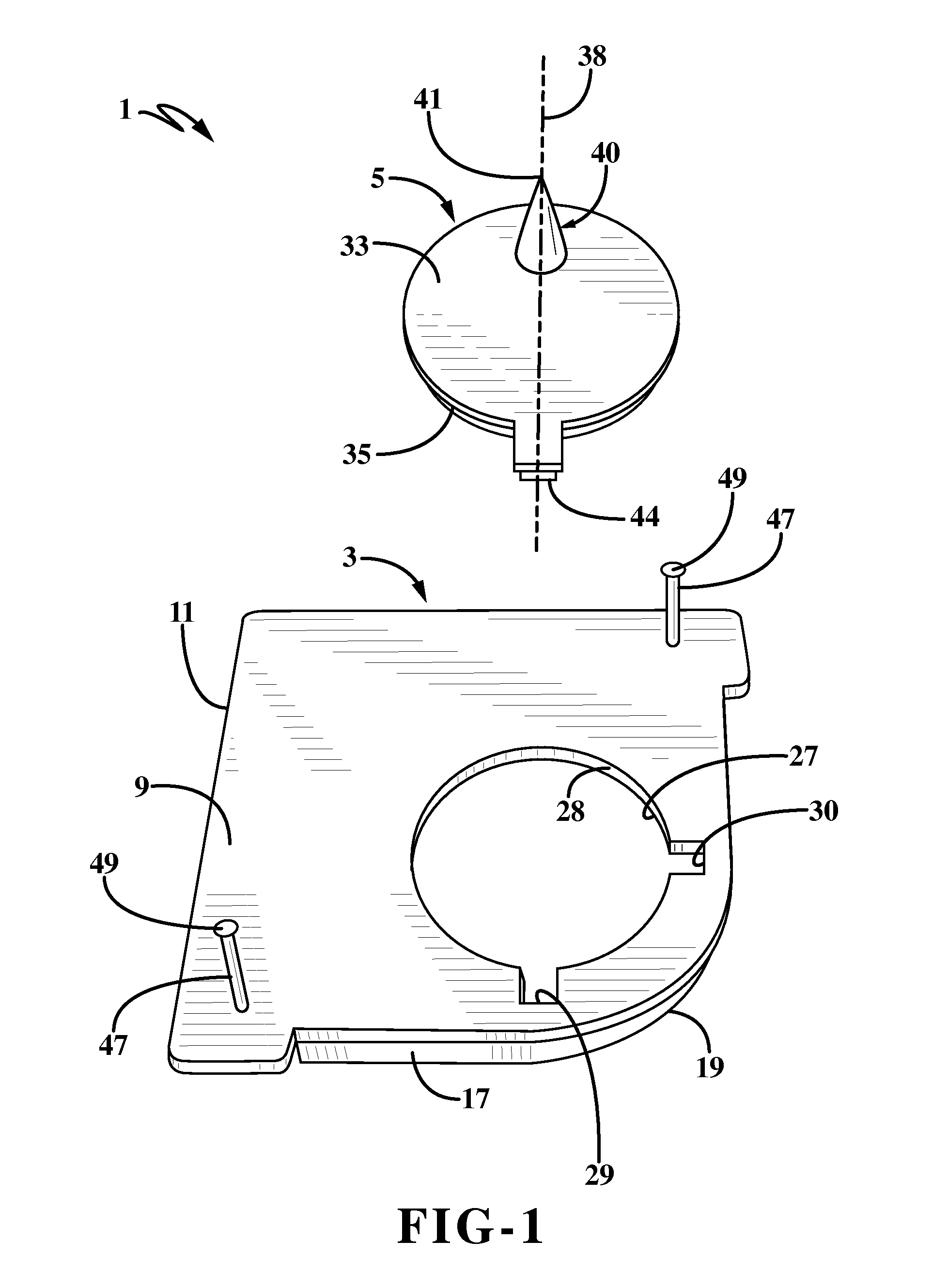
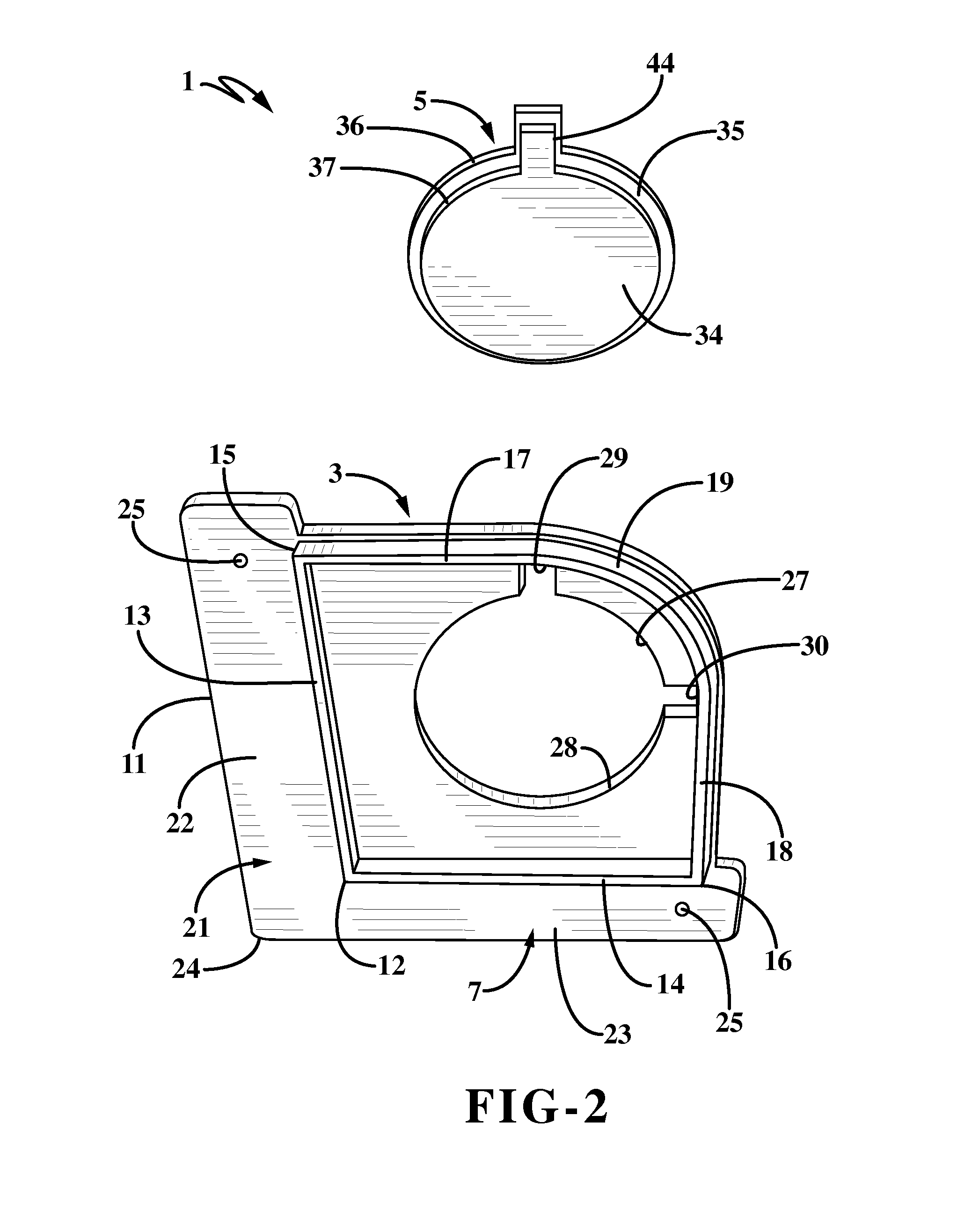
[0029]The apparatus of the present invention is indicated generally at 1, and is shown particularly in FIGS. 1-2. Apparatus 1 includes two main components, a bracket indicated generally at 3, and a marking device indicated generally at 5. Bracket 3 preferably is a one-piece member formed of a molded plastic material, although it could be multiple pieces without affecting the concept of the invention. Bracket 3 has a generally flat planar configuration which includes first and second opposed surfaces hereinafter referred to as bottom surface 7 and top surface 9 which terminate in an outer peripheral edge 11.

[0030]Top surface 9 (FIG. 1) is generally planar throughout its area, whereas bottom surface 7 (FIG. 2) has a pair of legs 13 and 14 which extend perpendicularly outwardly from surface 7 and join at an apex 12 forming a right angle corner therebetween. The terminal ends 15 and 16 of legs 13 and 14 respectively, are connected to a pair of straight sections 17 and 18 which are joine...


PUM


Abstract

An apparatus and method for hanging objects on a supporting wall includes a bracket with an outwardly extending shelf for supporting engagement with the object. A flange extends upwardly from the bracket and is secured by a fastener to the object. A marking device is removably mounted in an aperture formed in the bracket and has a sharp marking element extending therefrom. After the bracket is attached to the object by the fasteners and the marking element is positioned in the aperture, the object is pressed against the supporting wall at the desired hanging location whereupon the marking element marks the wall at the correct location for installing the hanging hardware. After the hanging hardware is installed at the marked locations, it is subsequently received in the bracket aperture after the marking element is removed therefrom to hang the object on the hanging hardware.

Description

CROSS REFERENCE TO RELATED APPLICATIONS[0001]This application is a continuation-in-part of U.S. patent application Ser. No. 14 / 842,128, filed Sep. 1, 2015; the disclosure of which is incorporated herein by reference.[0002]This application is a continuation-in-part of U.S. patent application Ser. No. 14 / 842,024, filed Sep. 1, 2015; the disclosure of which is incorporated herein by reference.BACKGROUND OF THE INVENTION[0003]Technical Field[0004]The invention relates to an apparatus for hanging objects such as picture frames, mirrors etc. onto a supporting wall or structure. More particularly, the invention relates to an apparatus and method of use for supporting an object on a wall wherein the apparatus includes a hanger bracket having a removably attached marking device which is used to mark the location on the wall where the hanging hardware is to be installed ensuring accurate placement of the object on the wall.[0005]Background Information[0006]One of the common problems in hangin...

Claims


Application Information

Patent Timeline
Patent Type & Authority Applications(United States)
IPC IPC(8): A47G1/20A47G1/16A47G1/06F16M13/02
CPCA47G1/205A47G1/06A47G1/1633F16M13/02A47G1/16A47G1/1606A47G1/162
Inventor KRAKE, KELLY R.TOUSIGNANT, LIETTEKURTZ, MICHAEL
Owner UNDER THE ROOF DECORATING
Learn More