Thin register

a register and thin technology, applied in the field of registers, can solve the problems of deterioration of the appearance, and deterioration of the directionality of the air blowing to the upside, so as to prevent deterioration in the appearance and improve the directionality of the wind

Inactive Publication Date: 2017-03-02
HOWA PLASTICS CO LTD
View PDF3 Cites 9 Cited by
  • Summary
  • Abstract
  • Description
  • Claims
  • Application Information

AI Technical Summary

Benefits of technology

[0010]It is an object of the present invention to provide a thin register capable of preventing deterioration in appearance and improving the directionality of wind when the front movable louver is turned to the upside.
[0013]According to this invention, when the front movable louver is brought into a neutral state to use the register, the auxiliary fin can be located inside of the recessed portion cover, which allows performing air blowing in the forward direction of the air outlet with less pressure loss. When the front movable louver is operated so as to turn to the upside, the distal end portion of the auxiliary fin projects into a passage through the opening of the recessed portion cover and acts so as to make the inclined surface of the distal end portion hit against an air flow and bend the air flow upward, which therefore allows blowing air obliquely upward and forward with excellent directionality.
[0015]Here, the above-described thin register may be constituted such that the air outlet of the register main body is formed, in terms of its front shape, to incline so as to retract an upper portion to the upstream side and project a lower portion to the downstream side. When the thin register is made into a slanted shape as its front shape to incline so as to retract an upper portion to the upstream side and project a lower portion to the downstream side, an air flow blown out from the air outlet is likely to flow along the surface of a bulging portion in front of and under the outlet due to the Coanda effect produced therein, but the register of the present invention can prevent the Coanda effect and blow an air flow oriented forward or upward with satisfactory directionality.

Problems solved by technology

However, the above-described thin register has had a problem that, when the front movable louver is turned, for example, to the upside, the central horizontal fin, the upper auxiliary horizontal fin, and the lower auxiliary horizontal fin all turn obliquely upward, but because the air outlet is in a vertically narrowed thin shape, the air blowing direction is unlikely to be oriented to the upside, and the directionality of air blowing is likely to deteriorate.
Therefore, in the bulging curved portion under and in front of the register, a sticking phenomenon of wind is likely to occur, and when the sticking phenomenon of wind occurs, an air flow blown from the air outlet along the front movable louver is guided to the downside, and the directionality of air blowing to the upside is likely to deteriorate.
Therefore, there has been a problem that a bottom portion in the retainer hollowed out in a recessed shape is easily viewed between the horizontal fins, which is likely to deteriorate the appearance.

Method used


Image

  • Thin register
  • Thin register
  • Thin register

Examples


Embodiment Construction

[0041]Hereinafter, the present invention will be described based on embodiments shown in the drawings. However, the present invention is by no means limited to the embodiments. Any modifications within the requirements of the claims or equivalents relating to the requirements should be included in the scope of the claims.

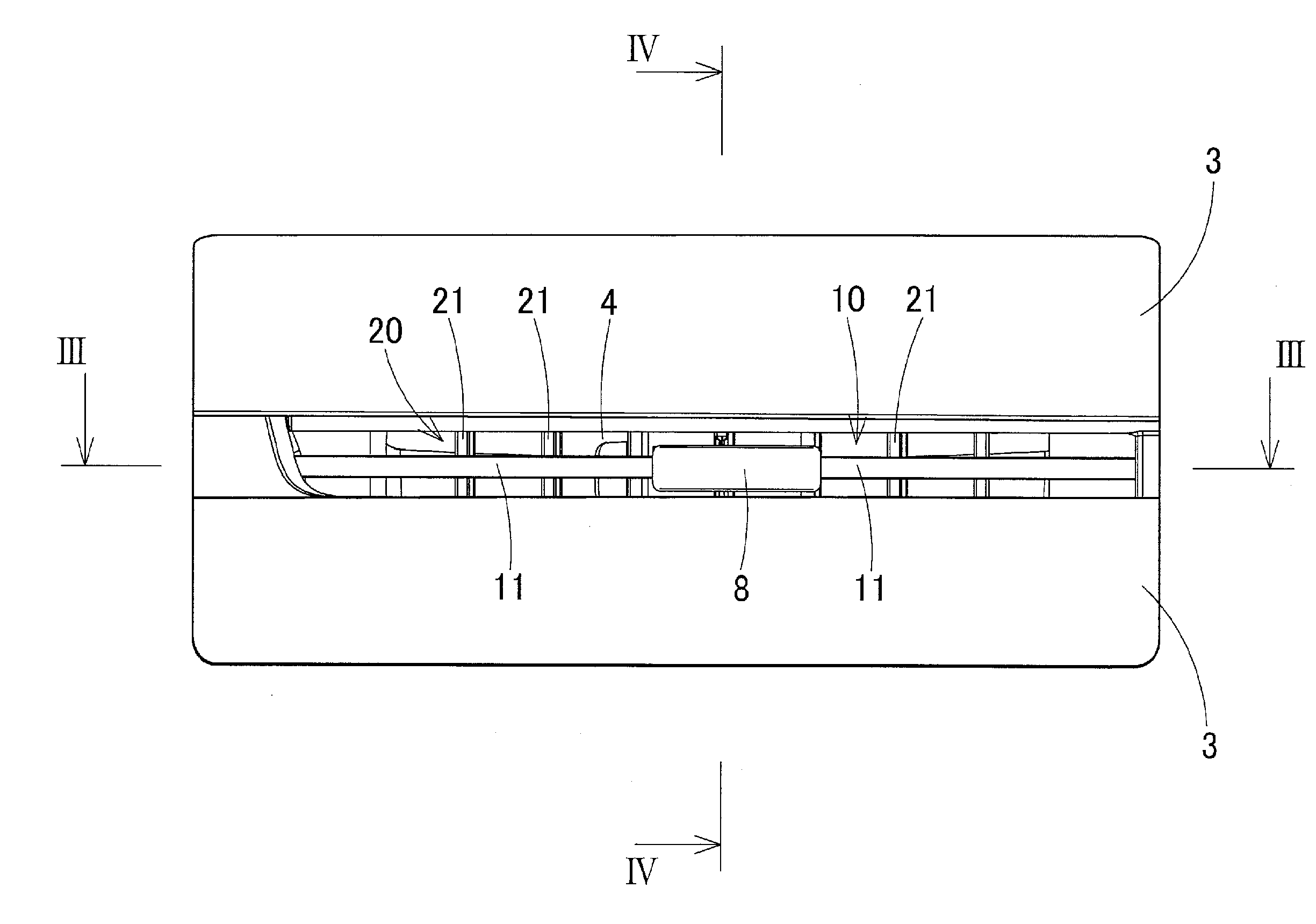
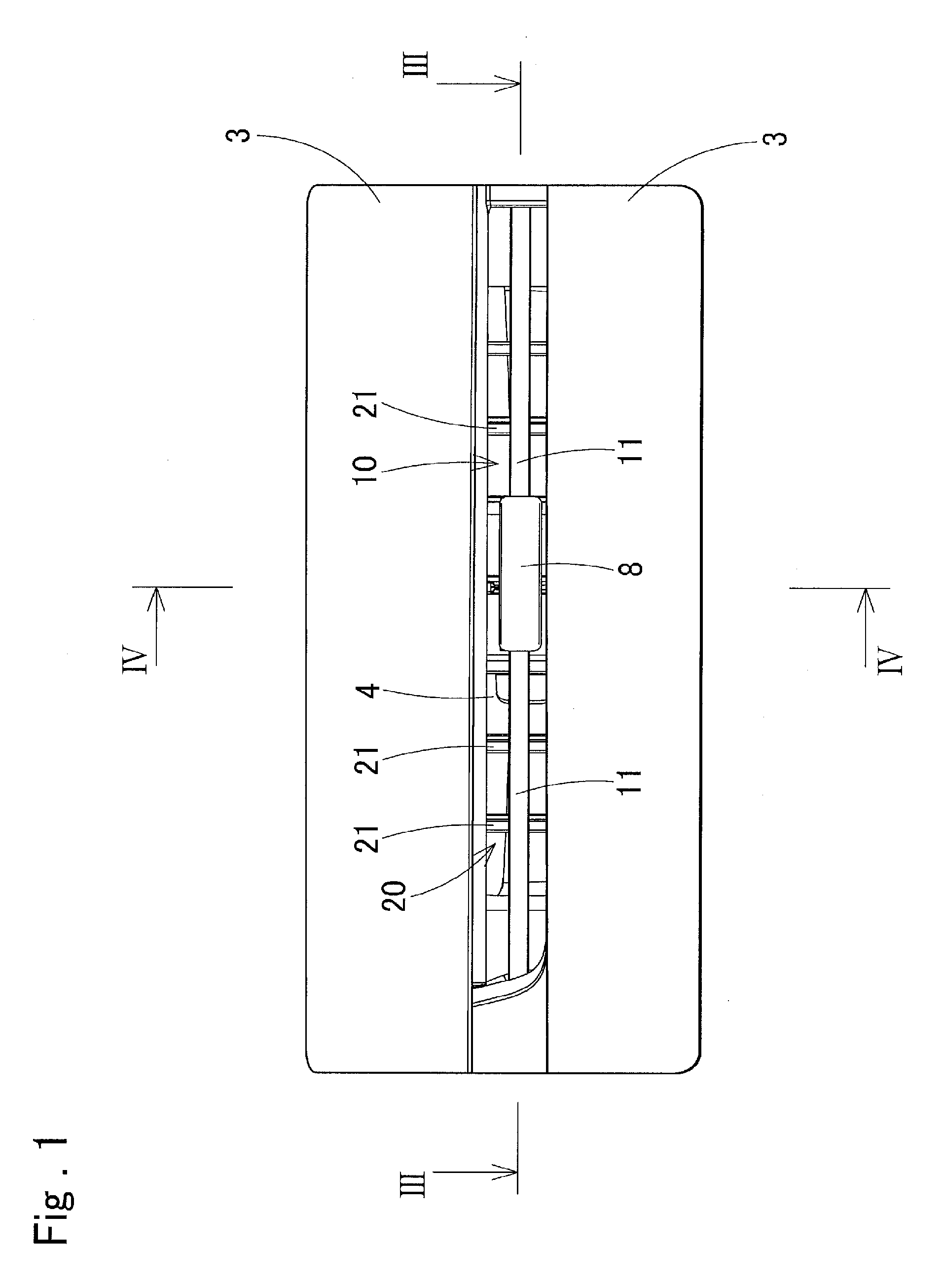
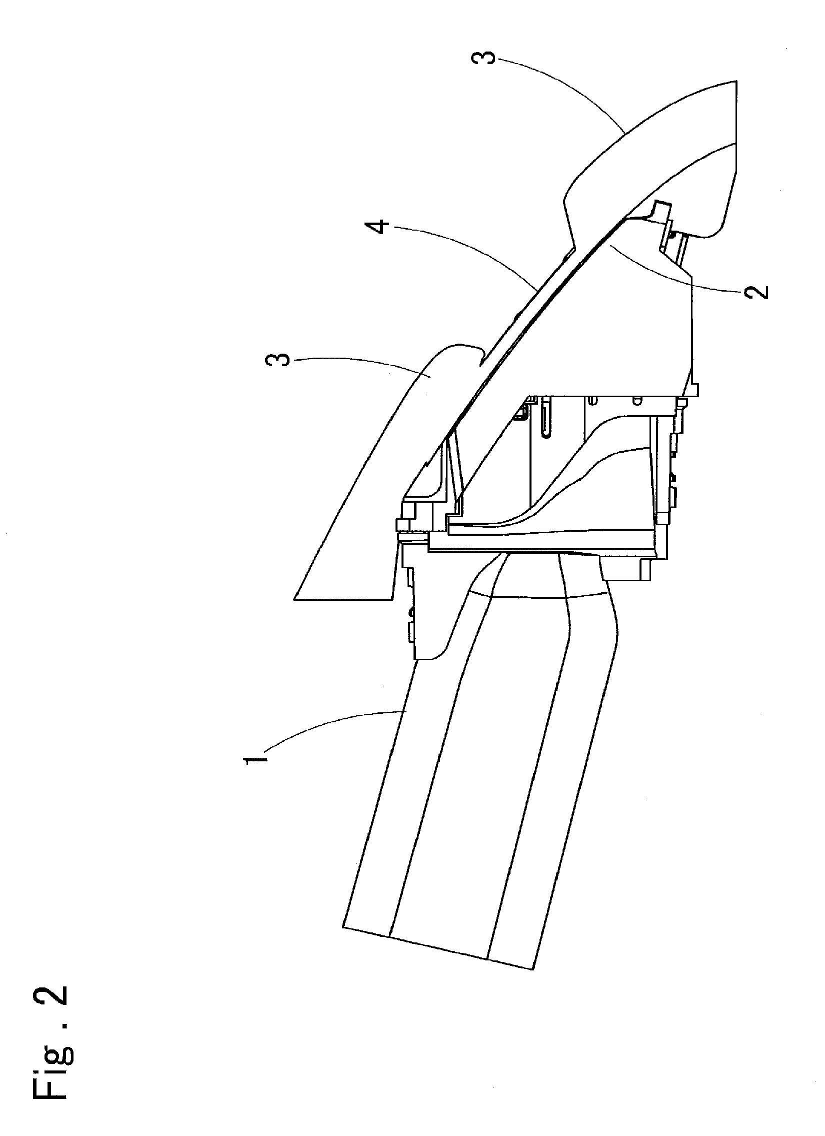
[0042]The thin register is constituted with a retainer 1 having inside an air passage 9 being formed in a vertically thin and flat duct shape, at the front of the retainer 1, a bezel 2 formed with an air outlet 4 in a narrow and long slit shape being attached, with a front movable louver 10 being disposed inside of an air outlet 4, and with a rear movable louver 20 being disposed in an air passage 9 that is on an upstream side of the front movable louver 10. The above-described register main body is composed of the retainer 1 and the bezel 2.

[0043]The front movable louver 10, as shown in FIG. 8, etc., includes a single front fin 11 and a single auxiliary fin 12 arra...


PUM


Abstract

A front fin of a front movable louver is axially supported immediately inside of an air outlet, and an auxiliary fin is axially supported in a recessed portion under the front fin. The front fin and the auxiliary fin are joined via a link member, and opposite side end portions at an upstream side of the auxiliary fin are axially supported via pivots. An inclined surface is provided on a distal end portion at a downstream side of the auxiliary fin. A recessed portion cover to overlay the recessed portion is attached to the recessed portion. When the front movable louver is operated so as to turn, the auxiliary fin turns so as to project its distal end portion upward through an opening in a front portion of the recessed portion cover and make the inclined surface of its distal end portion hit against an air flow flowing under the front fin.

Description

BACKGROUND OF THE INVENTION[0001]1. Field of the Invention[0002]The present invention relates to a register to be used for air blow adjustment of an air conditioner of an automobile, etc., and specifically, to a thin register having an air outlet that is vertically short and horizontally narrow and long.[0003]2. Description of Related Art[0004]As registers for air blow adjustment to be mounted on instrument panels or the like of automobiles, thin registers having air outlets that are vertically short and horizontally narrow and long have conventionally been known in JP2013-116650 A, etc.[0005]This register is constituted with a forwardly narrowing shape as a shape in terms of the vertical width of a bezel to be fitted to a front portion of a retainer, with an air outlet that is vertically short and horizontally narrow and long being provided at the front of the bezel, and with a front movable louver being disposed immediately inside of the air outlet. In the center of the front mova...

Claims


Application Information

Patent Timeline
Patent Type & Authority Applications(United States)
IPC IPC(8): B60H1/34B60H1/00
CPCB60H1/0065B60H1/3421B60H2001/3471
Inventor SHIBATA, AKIHIROMAKIMURA, HIDEKAZUMATSUZAWA, YOSUKE
Owner HOWA PLASTICS CO LTD
Why Eureka
Try Eureka