
Lightweight Collapsible Stroller

a lightweight, collapsible technology, applied in the field of strollers, can solve the problems of difficult movement between the collapsible (closed) positions of the stroller, the current stroller does not allow movement or folding, and the stroller generally lacks the improved functionality, structural stability, and stylish design. the effect of quick and easy transition

Inactive Publication Date: 2017-03-16
THORLEY INDS
View PDF6 Cites 8 Cited by
  • Summary
  • Abstract
  • Description
  • Claims
  • Application Information

AI Technical Summary

Benefits of technology

The present invention provides a lightweight stroller that can quickly and easily transition between open and closed positions. It includes a frame with a front and rear support, which are connected by a pivot joint. The frame also has a telescoping tube assembly with a slot and a linkage of rigid members connected between the two frames. The stroller also has a drive mechanism and a latch for transitioning between positions. The collapsible stroller has a frame with a movable portion and a latch for opening and closing, with a drive mechanism for transitioning between positions. The technical effects are that the stroller is easy to use, lightweight, and can be quickly and easily transitioned between open and closed positions.

Problems solved by technology

However, current strollers do not allow for movement or folding to compact configuration as desired, and are cumbersome and sometimes difficult to move between their collapsed (closed) positions and their operative (open) positions, particularly when attending to a baby or child.
However, lightweight strollers generally lack the improved functionality, structural stability, and stylish design which users expect from larger heavier models.

Method used


Image

  • Lightweight Collapsible Stroller
  • Lightweight Collapsible Stroller
  • Lightweight Collapsible Stroller

Examples


Embodiment Construction

[0081]For purposes of the description hereinafter, the terms “upper”, “lower”, “right”, “left”, “vertical”, “horizontal”, “top”, “bottom”, “lateral”, “longitudinal”, and derivatives thereof shall relate to the invention as it is oriented in the drawing figures. However, it is to be understood that the invention may assume alternative variations and step sequences, except where expressly specified to the contrary. It is also to be understood that the specific devices and processes illustrated in the attached drawings, and described in the following specification, are simply exemplary embodiments of the invention. Hence, specific dimensions and other physical characteristics related to the embodiments disclosed herein are not to be considered as limiting.

Power Folding Stroller

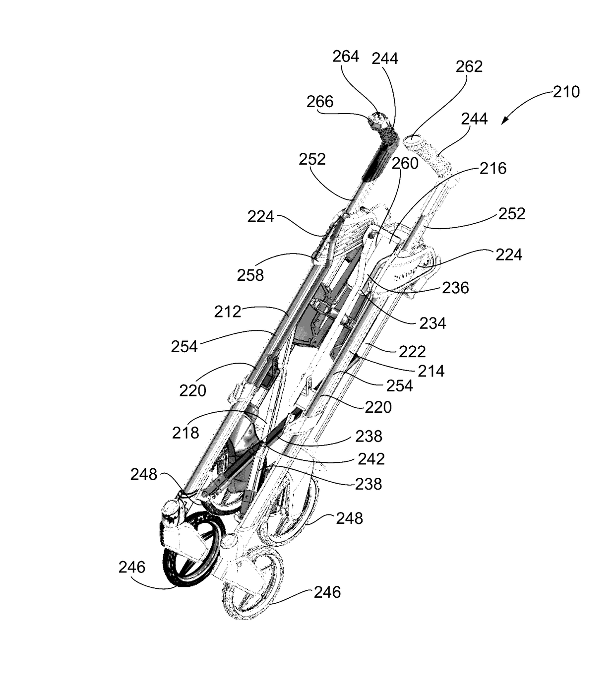
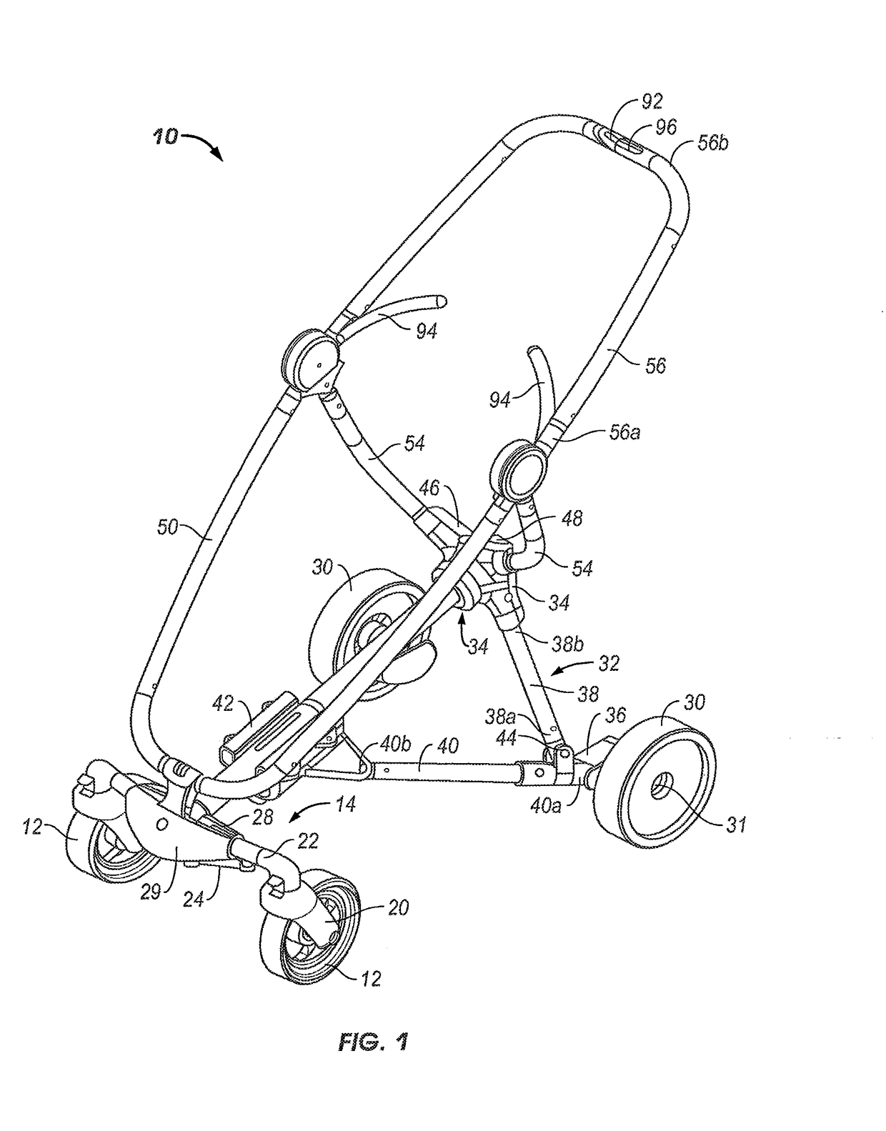
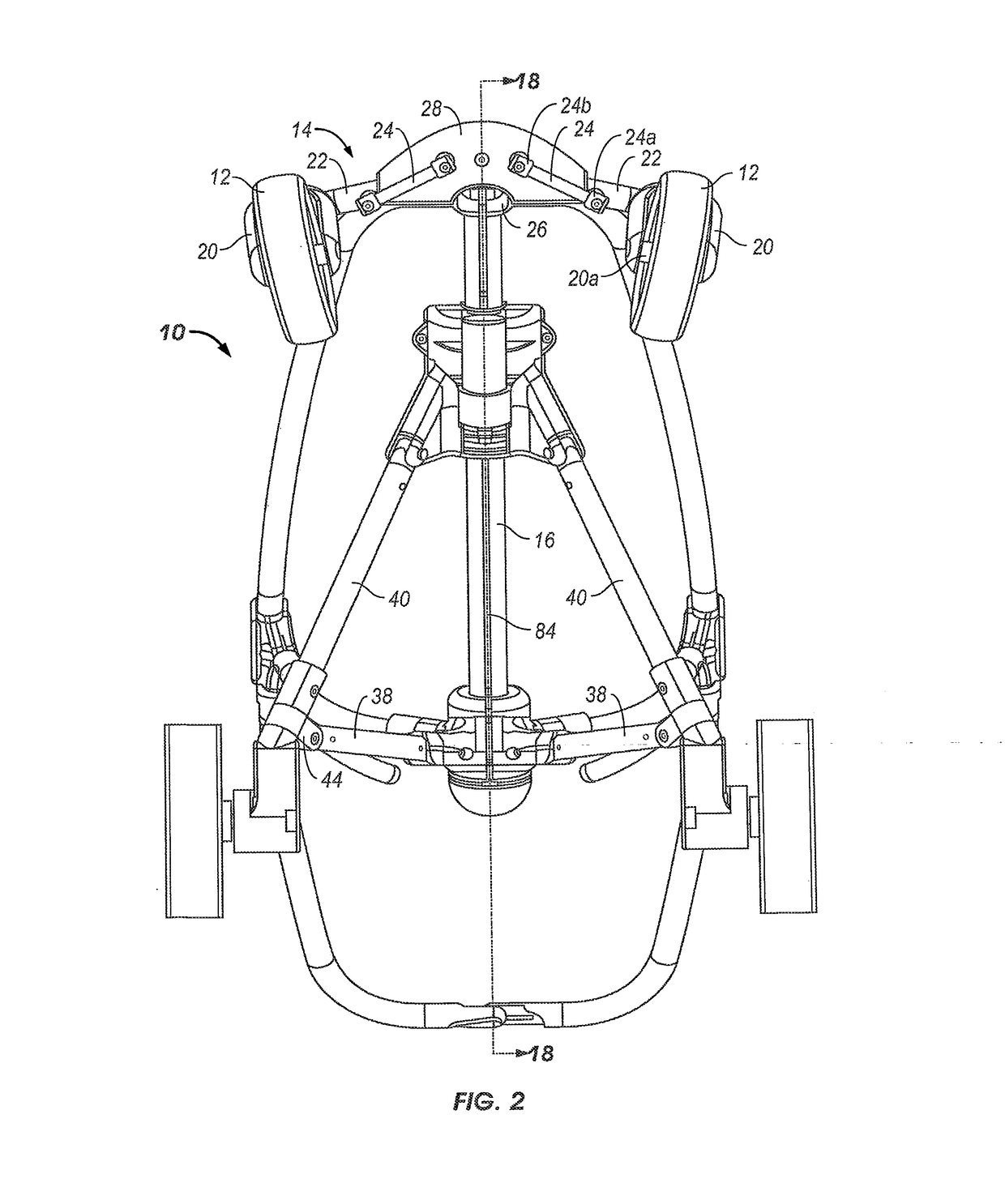
[0082]With reference to FIGS. 1-4 a stroller 10 is illustrated which comprises a pair of front wheels 12 having a front wheel support structure 14 for supporting the front wheels 12. The front wheel support struc...


PUM


Abstract

A lightweight collapsible stroller is provided. The stroller includes: a frame including a first portion movable relative to a second portion; a drive mechanism coupled to the frame, which moves the first portion relative to the second portion, thereby transitioning the frame between an open position and a closed position; and a latch mounted to the frame. The latch is positioned to engage at least a portion of the first portion or the second portion when the frame is in its open position to restrict the first portion from moving relative to the second portion. Upon actuation, the drive mechanism causes the latch to release, such that the first portion of the frame moves relative to the second portion of the frame, thereby allowing the frame to transition to the closed position.

Description

CROSS REFERENCE TO RELATED APPLICATIONS[0001]This application is: a continuation-in-part of U.S. patent application Ser. No. 14 / 660,342, filed Mar. 17, 2015, which is a continuation-in-part of U.S. patent application Ser. No. 14 / 581,094, filed on Dec. 23, 2014, which issued as U.S. Pat. No. 9,446,779 on Sep. 20, 2016, which is a continuation of U.S. patent application Ser. No. 13 / 672,038, filed Nov. 8, 2012, which issued as U.S. Pat. No. 8,944,457 on Feb. 3, 2015, which claims priority to U.S. Provisional Patent Application No. 61 / 557,694 filed on Nov. 9, 2011; and a continuation-in-part of U.S. patent application Ser. No. 13 / 109,328, filed May 17, 2011, which is a continuation of U.S. patent application Ser. No. 12 / 032,370, filed Feb. 15, 2008, now abandoned, which claims priority to U.S. Provisional Application No. 60 / 890,597, filed Feb. 19, 2007; 60 / 890,601, filed Feb. 19, 2007; 60 / 890,605, filed Feb. 19, 2007; 60 / 890,607, filed Feb. 19, 2007; 60 / 890,608, filed Feb. 19, 2007; 60 / ...

Claims


Application Information

Patent Timeline
Patent Type & Authority Applications(United States)
IPC IPC(8): B62B7/06B62B9/26B62B7/08B62B7/00
CPCB62B7/068B62B7/006B62B7/066B62B2205/02B62B7/086B62B2205/003B62B9/26B62B7/08B62B2205/06B62B2205/18B62B7/06B62B9/00B62B9/10
Inventor THORNE, HENRY F.DALEY, ROBERT D.HOPKE, FREDERICK KARLREMBISZ, JUSTINEWALKER, JOHN J.WIEGMANN, ELIJAH M.KOES, MARY J.
Owner THORLEY INDS
Learn More