Foundation for installation and positioning of automatic meteorological station

An automatic weather station, installation and positioning technology, applied in infrastructure engineering, construction, etc., can solve problems such as difficult construction and difficult implementation, and achieve the effect of convenient connection, convenient assembly, and enhanced integrity

Inactive Publication Date: 2016-09-21
NO 63655 TROOPS OF THE CHINESE PEOPLES LIBERATION ARMY
View PDF4 Cites 2 Cited by
  • Summary
  • Abstract
  • Description
  • Claims
  • Application Information

AI Technical Summary

Problems solved by technology

For construction in remote areas, such as mountains, deserts, islands, etc., it is difficult to implement on-site cement pouring, and the construction is very difficult

Method used


Image

  • Foundation for installation and positioning of automatic meteorological station
  • Foundation for installation and positioning of automatic meteorological station
  • Foundation for installation and positioning of automatic meteorological station

Examples


Embodiment 1

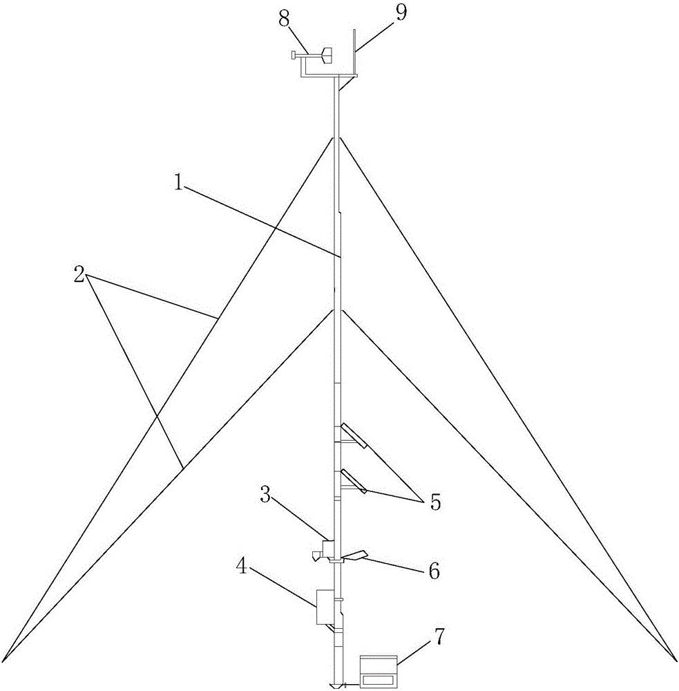
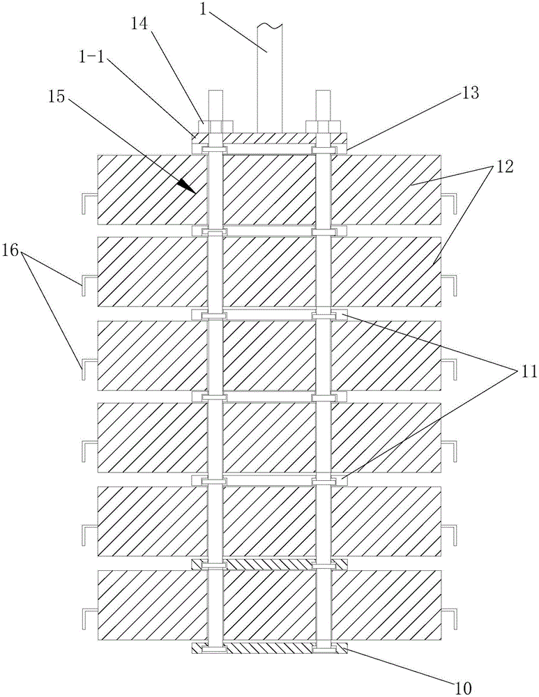
[0045] Such as figure 2 The shown foundation for installing and positioning an automatic weather station includes a prefabricated counterweight set in the foundation pit, the lower end of the prefabricated counterweight is supported on the bottom of the foundation pit, and the upper end of the prefabricated counterweight It is connected with the lower end of the central wind rod 1 of the automatic weather station, the lower end of the guy line 2 of the automatic weather station or the rain gauge of the automatic weather station.

[0046] In this embodiment, the foundation is used for the installation and positioning of the central mast 1 of the automatic weather station. When installing and positioning the central air pole 1, the prefabricated counterweight is placed in the pre-dug foundation pit, and then the lower end of the central air pole 1 is connected with the prefabricated counterweight to achieve The installation and positioning of the central wind pole 1 of the aut...

Embodiment 2

[0060] Such as Figure 9 As shown, the difference between this embodiment and Embodiment 1 is that the upper end of the prefabricated counterweight is connected to the lower end of the stay wire 2 of the automatic weather station. That is, the foundation is used for the installation and positioning of the automatic weather station backguy 2. When the backguy 2 is installed and positioned, the prefabricated counterweight is placed in the pre-dug foundation pit, and then the lower end of the backguy 2 is connected to the The prefabricated counterweights are connected to achieve the installation and positioning of the central wind pole 1 of the automatic weather station, thereby avoiding the difficulty of making the foundation temporarily through cement casting on site, which is especially suitable for remote areas, such as Construction in areas such as mountains, wilderness and islands.

[0061] Such as Figure 9 As shown, an eye nut 17 is installed on the screw 15-2 of the co...

Embodiment 3

[0065] Such as Figure 10 As shown, the difference between this embodiment and Embodiment 1 is that: the upper end of the prefabricated counterweight is connected to the rain gauge of the automatic weather station. That is, the foundation is used for the installation and positioning of the rain gauge of the automatic weather station. When the rain gauge is installed and positioned, the prefabricated counterweight is placed in the pre-dug foundation pit, and then the lower end of the rain gauge The base plate 19 is connected with the prefabricated counterweight, which achieves the installation and positioning of the base plate 19 of the automatic weather station, thereby avoiding the difficulty of making the foundation temporarily by pouring cement on site, which is especially suitable for remote areas. Construction in areas such as mountains, wilderness and islands.

[0066] In this embodiment, the top plate 13 is closely attached to the base plate 19 at the lower end of the ...


PUM


Abstract

The invention discloses a foundation for installation and positioning of an automatic meteorological station. The foundation includes a prefabricated balancing weight arranged in a foundation pit; the lower end of the prefabricated balancing weight is arranged on the bottom of the foundation pit, and the lower end of the prefabricated balancing weight is connected to the lower end of a central wind rod of the automatic meteorological station, the lower end of a pull rope of the automatic meteorological station or a rain gauge of the automatic meteorological station. The foundation is easy to prepare, is easy to install, can effectively avoid the situation that a foundation is temporarily fabricated by cement cast-in-place, and is especially suitable for construction of remote areas such as high mountains, wildernesses, and sea islands.

Description

technical field [0001] The invention relates to the technical field of automatic weather station installation and positioning, in particular to a foundation for automatic weather station installation and positioning. Background technique [0002] Automatic weather stations have been widely used in various fields such as military affairs and people's livelihood. Automatic weather stations generally include a central wind pole 1, a backguy 2 and a rain gauge. The upper end of the center wind rod 1 is connected to the upper part, the lower end of the stay wire 2 is connected to the cement pouring foundation, the rain gauge and the central wind rod 1 are separately set, and the rain gauge is fixed on the cement pouring foundation. In addition, The solar panel 5 for meteorological detection, the visibility sensor 6, the louver cover 3 and the collection box 4 and the battery box 7 for supplying power to the above-mentioned devices are arranged on the central wind pole 1, and the ...

Claims


Application Information

Patent Timeline
Patent Type & Authority Applications(China)
IPC IPC(8): E02D27/42
CPCE02D27/42
Inventor 关军文元宏任莉唐敬李晓辉王朴军郑伟静王建华秦洪才
Owner NO 63655 TROOPS OF THE CHINESE PEOPLES LIBERATION ARMY
Why Eureka
Try Eureka