Mounting bracket for scope of a gun

a technology for mounting brackets and guns, applied in the field of mounting brackets of guns, can solve the problems of inability to meet the rapid changes required in battlefield conditions, laborious and time-consuming, and inability to quickly disassemble, and achieve the effect of reducing the drawbacks of conventional mounting brackets and rapid disassembly

Inactive Publication Date: 2005-08-02
THE 401ST PLANT MATERIEL PRODION CENT ARMAMENTS BUREAU M N D
View PDF8 Cites 103 Cited by
  • Summary
  • Abstract
  • Description
  • Claims
  • Application Information

AI Technical Summary

Benefits of technology

[0010]Accordingly, it is an object of the present invention to provide a mounting bracket for the scope of a gun which mitigates the drawbacks of the conventional mounting bracket.
[0011]An aspect of the present invention is to provide a mounting bracket comprising a seat body, an actuating jaw and a triggering block, wherein the top face of the seat body is a securing seat for mounting scopes, and one side of the seat body is downwardly extended to a securing jaw and the inner face of the securing jaw is a notch corresponding to the sliding rail, and the seat body at the opposite side of the securing jaw is a circular pivotal path which can be pivotally mounted with an actuating jaw, and the top edge of the seat body is protrudingly extended to form an inverted L-shaped suspension lug and the triggering block is pivotally positioned between two suspension lugs; the actuating jaw corresponding to the inner face at one side of the securing jaw is provided with a notch and the top edge of the actuating jaw is a pivotal rail which can pass through the pivotal path, and the external side face of the actuating jaw is an urging face for stopping the triggering block; and the top edge of the triggering block having an inverted L-shaped body is an urging block corresponding to the actuating jaw, the urging block of the triggering block is pivotally mounted at the suspension lug of the seat body and the distance between the end face of the urging block to the pivot point center is longer than the distance from the top face to the pivot point center and the triggering block can tightly urge or release the actuating jaw.
[0012]Yet another object of the present invention is to provide a mounting bracket for the scope of a gun, wherein the mounting bracket and the barrel can be rapidly disassembled and the direction of action of the triggering block is perpendicularly intersected with the vibration direction of the barrel and therefore the mounting bracket will not be dislocated in the course of shooting.

Problems solved by technology

[1] Laborious in assembly and disassembly: The actuating jaw 25 has to be fully dislocated from the sliding rail 15 in order to unload the mounting bracket, the locking element 28 has to be loosened for a longer period of time and it is laborious and time consuming.
It is not practical in view of rapid changes required in battlefield conditions.
However, if it is tightened too strongly, the locking element 28 can be easily damaged and moreover, it will take a longer time to tighten.

Method used


Image

  • Mounting bracket for scope of a gun
  • Mounting bracket for scope of a gun
  • Mounting bracket for scope of a gun

Examples


Embodiment Construction

[0020]The following descriptions are of exemplary embodiments only, and are not intended to limit the scope, applicability or configuration of the invention in any way. Rather, the following description provides a convenient illustration for implementing exemplary embodiments of the invention. Various changes to the described embodiments may be made in the function and arrangement of the elements described without departing from the scope of the invention as set forth in the appended claims.

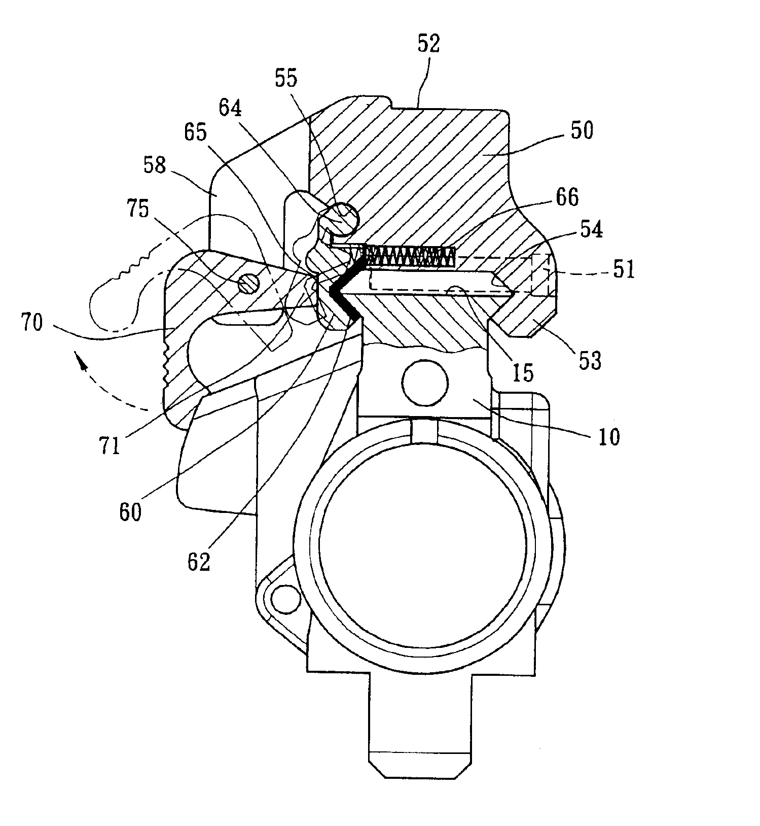
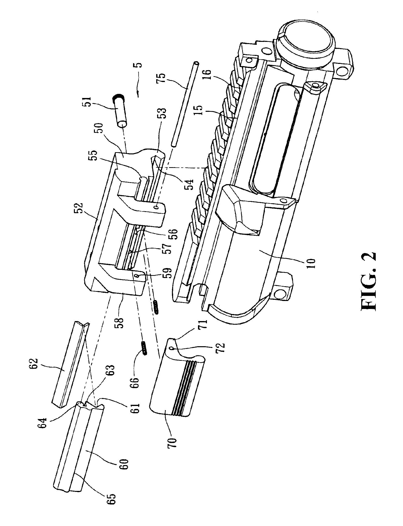
[0021]FIG. 2 shows the mounting bracket for the scope of a gun in accordance with the present invention. As shown in the figure, the mounting bracket 5 comprises a seat body 50, an actuating jaw 60 and a triggering block 70 for mounting a scope, which is then positioned onto a sliding rail 15 of the barrel 10 of the gun.

[0022]Referring to FIGS. 2 and 3, the top face of the seat body 50 is a securing seat 52 for mounting various types of scopes such as telescopic scopes or night scopes, etc. One s...


PUM


Abstract

A mounting bracket for a scope of a gun is disclosed. The mounting bracket is used to mount night scopes or telescopic scopes onto the barrel of a gun rapidly. The bracket comprises a seat body having a securing jaw, an actuating jaw and a triggering block, and the actuating jaw is pivotally mounted at the seat body and, together with the securing jaw, correspondingly grips the barrel of the gun. Further, the triggering block is pivotally mounted at the seat body, and the triggering block correspondingly urges or releases the actuating jaw. The user can rapidly disassemble the mounting bracket and the barrel of the gun. The direction of action of the triggering block is perpendicularly intersected with the vibration direction of the barrel and therefore the mounting bracket will not be dislocated in the course of shooting.

Description

BACKGROUND OF THE INVENTION[0001](a) Technical Field of the Invention[0002]The present invention relates to a mounting bracket of a gun, and in particular, to a mounting bracket for a telescopic scope or night scope which can be rapidly loaded or unloaded onto the barrel of the gun without dislocation.[0003](b) Description of the Prior Art[0004]For guns capable of long-stance shooting, such as rifles or machine guns, in order to enhance shooting accuracy or use of the guns in an unfavorable environment, a scope, telescopic sight or night scope are mounted. Therefore, the specification for the mounting of the scope tends to be standardized so that the loading and unloading can be rapidly carried out. Thus, a mounting bracket is generally used to mount the scope onto the barrel of a gun. FIG. 1 is a conventional mounting bracket 20 which is mounted at the two lateral sides of the barrel 10. A sliding rail 15 is formed on the side edge and there are positioning slots 16 on the sliding ...

Claims


Application Information

Patent Timeline
Patent Type & Authority Patents(United States)
IPC IPC(8): F41G1/387F41G1/00
CPCF41G11/003
Inventor HUAN, CHE KUM
Owner THE 401ST PLANT MATERIEL PRODION CENT ARMAMENTS BUREAU M N D
Why Eureka
Try Eureka