Flexible articulated device
Inactive Publication Date: 2017-03-30
LARYNGOPORT
1 Cites 0 Cited by
AI-Extracted Technical Summary
Problems solved by technology
These kind of procedures are usually performed with rigid shafts that are less suitable to accommodate the tortuous pathway of the body lumen.
Current laryngoscopy devices do not utilize articulating effectors to provide the user with more control over the orientation of the working end of the instrument.
Integration of the controls for articulating, as well as actuating, tend be complicated by the siz...
Method used
[0046]In certain embodiments, the end effector can rotate relative to the elongate shaft of the device, and/or the shaft can rotate relative to a handle of the device. Articulation and rotation of the end effector will allow the end effector to be positioned at various locations during a surgical procedure, thereby providing the user with precise control over the end effector. Furthermore, in the present invention, the novel clevis provides further control on the flexible shaft, while actuating, rotating and articulating, in an independent way. A person skilled in the art will appreciate that the present invention has application in laryngoscopy procedures.
[0049]FIG. 3 illustrates the configuration of the clevis 170. In the upper level of the clevis there is a slit 171 in which the second link 150 can move when the coil shaft 140 is being retracted. Before the distal part of the clevis there is a guide 172 that is responsible for separating the zone where the actuation wire passes 174 and the zone where the second link 150 moves. On the distal part of the clevis there are the slots 173 for the insertion of the connecting pins between the clevis 170 and the effector 160. The guide 172 is configured having, by at least a section of a shape characterized as a concaved-parabolic nozzle-like form. Exemplary diagram 175, is an idealized version of such a nozzle-like form. It is herein acknowle...
Benefits of technology
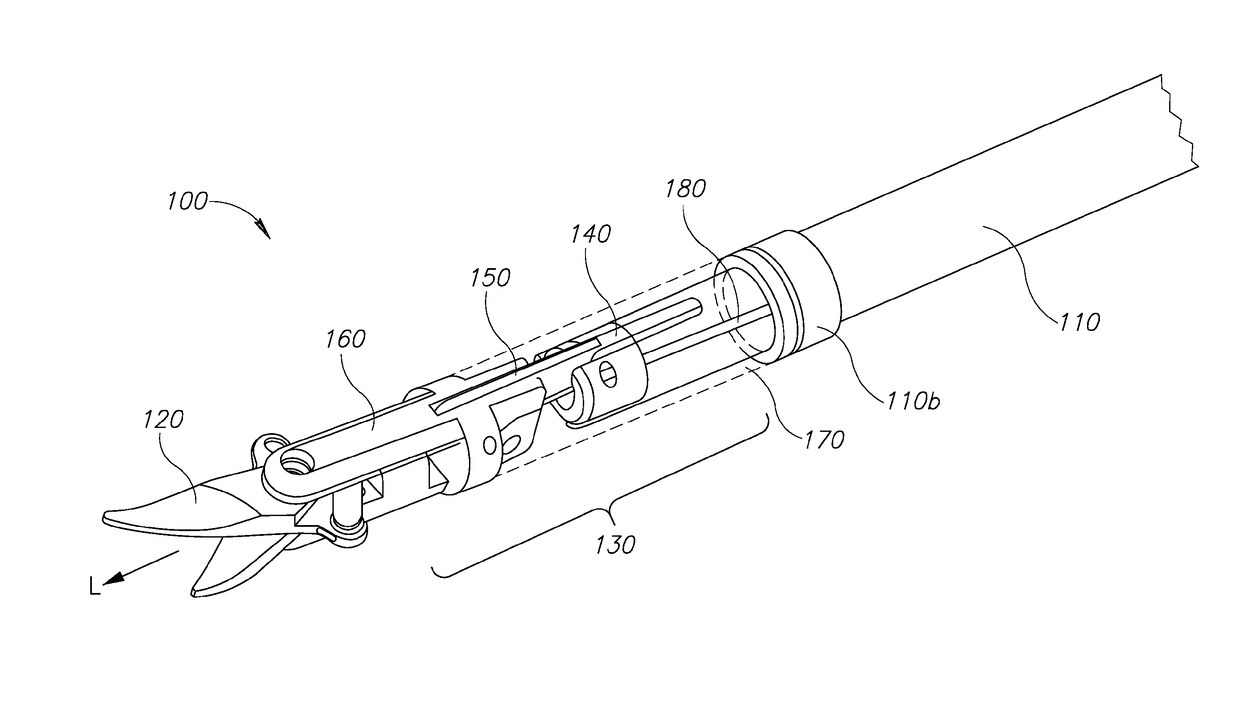
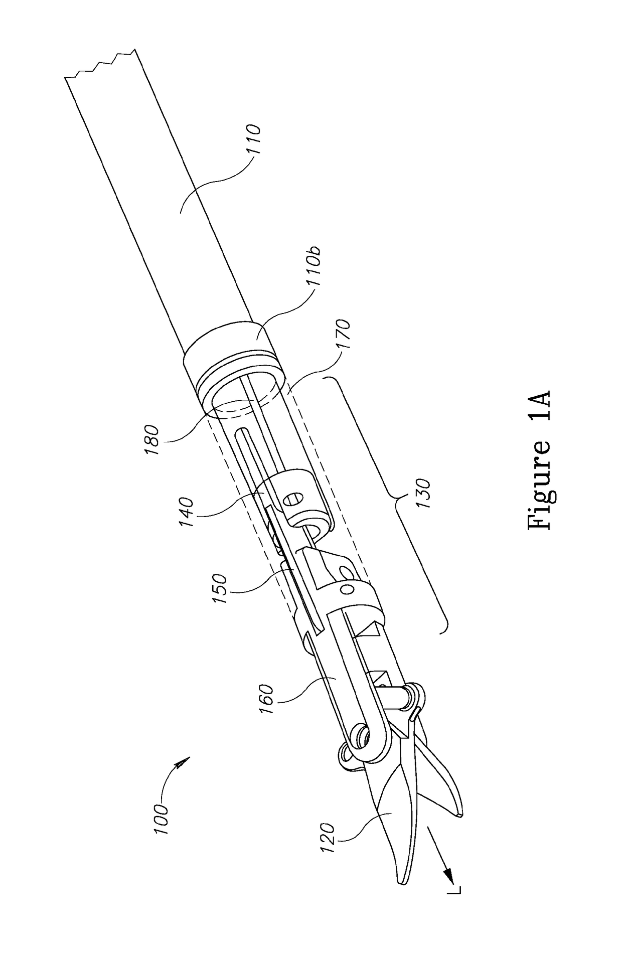
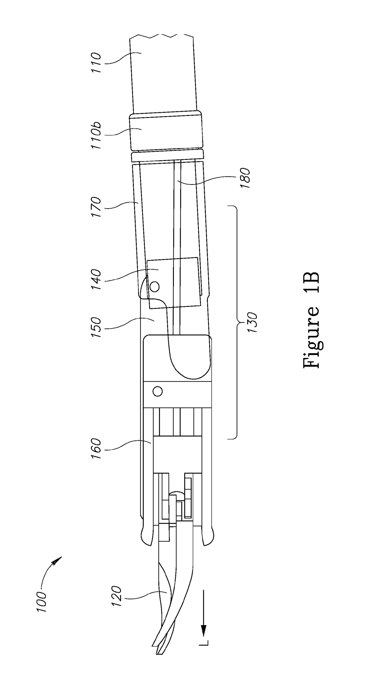
[0005]It is an object of the present invention to provide a surgical device comprising a three-bar-linkage retraction mechanism, said mechanism comprises a distal element 160, link 150 and a flexible elongated (endless) shaft 110 pro...
Abstract
The present innovation pertains to a device and method for enabling movement of a flexible medical device.
Application Domain
Surgical manipulatorsSurgical forceps
Technology Topic
Biomedical engineeringMedical treatment +1
Image
Examples
- Experimental program(1)
Example
[0042]Certain exemplary embodiments will now be described to provide an overall understanding of the principles of the structure, function, and use of the devices and methods disclosed herein. One or more examples of these embodiments are illustrated in the accompanying drawings. Those skilled in the art will understand that the devices and methods specifically described herein and illustrated in the accompanying drawings are non-limiting exemplary embodiments and that the scope of the present invention is defined solely by the claims. The features illustrated or described in connection with one exemplary embodiment may be combined with the features of other embodiments. Such modifications and variations are intended to be included within the scope of the present invention.
[0043]The instrument is configured for containing or carrying medical tools and/or surgical objects at the distal segment. Optionally, medical tools and/or surgical objects (hereinafter, referred to collectively as “medical tools”) are contained within the distal segment. Alternatively or additionally, one or more medical tools are attached to an end of the distal segment. Alternatively or additionally, the medical tool(s) can be inserted into the distal portion during maneuvering thereof and deployed when needed. Alternatively or additionally, a conduit or the like is inserted through the proximal and distal segments for injection of medication or collecting of tissue samples.
[0044]The present invention provides methods and devices for enhancing control on movement of a working end of a surgical device, and in particular for performing various surgical procedures using an instrument having an end effector that can be articulated relative to a flexible elongate shaft of the device.
[0045]The present invention provides a flexible shaft with a novel configuration. The novel device described herein has a flexible configuration shaft enabling three degrees of freedom to be achieved for rotation, actuation and articulation independent of each other.
[0046]In certain embodiments, the end effector can rotate relative to the elongate shaft of the device, and/or the shaft can rotate relative to a handle of the device. Articulation and rotation of the end effector will allow the end effector to be positioned at various locations during a surgical procedure, thereby providing the user with precise control over the end effector. Furthermore, in the present invention, the novel clevis provides further control on the flexible shaft, while actuating, rotating and articulating, in an independent way. A person skilled in the art will appreciate that the present invention has application in laryngoscopy procedures.
[0047]FIGS. 1a-b illustrates one explanatory embodiment of an insertion portion 100 of an either manually and/or mechanically articulating flexible device. The insertion portion 100 is preferably configured to be inserted into a patient's body, and it has rigid and flexible portions. As shown, the insertion portion 100 generally comprises a hollow flexible elongate shaft 110 coupled to a distal end 110b thereof by a three-bar linkage/clevis part 130, ending with a working end or end effector 120. While the end effector 120 can have various configurations, in the illustrated embodiment the end effector 120 is in the form of scissors having opposed jaws that are pivotally coupled to one another. The three-bar linkage/clevis 130 allows the end effector 120 to be oriented at an angle relative to a longitudinal axis L of the elongate shaft 110. The device is also configured to allow the end effector 120 to rotate relative to and about the longitudinal axis L of the elongate shaft 110. An actuation wire 130 goes through the hollowed coiled shaft, via the clevis, to the end effector.
[0048]FIG. 2 illustrates one detailed explanatory embodiment. The three-bar linkage is composed by 4 distinct parts pivotally linked to each other: the coiled shaft 140, the second link 150, the end effector base 160 and the clevis 170. Rotation of the end effector is allowed by the coiled shaft 140, which is accommodated within the elongated flexible hollowed shaft 110. The distal end of the coiled shaft 140 is pivotally coupled to the clevis 170. So when the coiled shaft rotates, also the whole end (comprising of the clevis, the three-bar linkage and the end effector) turn as well. Each link can have a variety of configurations, but in an exemplar embodiment the first link is the coiled shaft 140. The second link 150 have a generally elongate shape and the third link 160 is in the form of an elongate rod or bar. The coiled shaft 140, is coupled in its distal end 140b to an adaptor 141. Adaptor 141 is coupled by a pin to a proximal end of the second link 150a. The distal end 150b of the second link 150 is coupled by a pin to a proximal end 160a of the effector base 160. The distal end 110b of the flexible shaft 110 is coupled to a rotating adaptor 111 which is successively coupled to the proximal end 170a of the clevis 170. The distal end of the clevis 170b is coupled by a pin to the proximal end 160a of the base of the end effector 160. The actuation wire 180 is accommodated within the coiled shaft 140 into the clevis 170, being separated from the second link 150 by the guide 172 (in FIG. 3). From there, the distal end 180b of the actuation wire 180 goes into the end effector 160, in which different types of tools can be configured, as shown in FIGS. 1a-b 120. The particular location, at which the base of the end effector 160 mates to the second link 150 and the clevis 170, is pivotally mated at a location that will allow the base of the en effector 160 to articulate relative to the coil system 140. This occurs when the coil system 140 is retracted.
[0049]FIG. 3 illustrates the configuration of the clevis 170. In the upper level of the clevis there is a slit 171 in which the second link 150 can move when the coil shaft 140 is being retracted. Before the distal part of the clevis there is a guide 172 that is responsible for separating the zone where the actuation wire passes 174 and the zone where the second link 150 moves. On the distal part of the clevis there are the slots 173 for the insertion of the connecting pins between the clevis 170 and the effector 160. The guide 172 is configured having, by at least a section of a shape characterized as a concaved-parabolic nozzle-like form. Exemplary diagram 175, is an idealized version of such a nozzle-like form. It is herein acknowledged that the guide section may be configured in variations of the concaved-parabolic nozzle-like form. The nozzle-like shape is configured for guidance of the actuation wire and facilitates longitudinal motion of the wire but prevents side to side motion of same.
[0050]FIGA illustrates a possible configuration of the second link 150. Usually, the second link in a three-bar linkage is made of a single, elongated piece, which is pin connected to the other links. The novel configuration of the second link comprises the division of the second link 150 into three distinct parts 150.1, 150.2, 150.3, connected to each other by pins. This configuration enables a higher articulation angle of the end effector when needed.
[0051]As indicated above, the embodiment disclosed herein for enabling movement of a working end of a surgical device is used in a variety of laryngoscopy surgical procedures. In one exemplary laryngoscopy procedure, a surgical device comprising three-bar-linkage retraction mechanism, in which said mechanism comprises a distal element 160, a link 150 and a flexible elongated shaft 110 provided proximally to the three link bar, wherein the link is interconnected to the shaft, by mean of a rigid clevis 170. Further comprising the device a flexible coiled rotation-enabling shaft 140 that is accommodated within the main flexible shaft 110 and part of its distal end is accommodated within the clevis 170. An actuation wire 180 accommodated within the coiled shaft 140 extends through the clevis 170, via the guide 172, into a part of the end effector 160.
[0052]Reference is now made to FIG. 5 which is an illustration of the method of operating the device. The method comprises steps of:
[0053]Articulation [0054] a. Retraction of coiled shaft 140, within clevis 170; [0055] b. Retraction of adaptor 141 by coiled shaft 140; [0056] c. Second link 150 is pulled back by adaptor 141; [0057] d. Effector 160 is pulled up by second link 150, enabled by interconnection with clevis [0058] 170;
[0059]Rotation [0060] a. Rotation of coiled shaft 140, within main shaft 110 (not shown); [0061] b. Rotation of adaptor 141 by coiled shaft140; [0062] c. Second link 150 is rotated by adaptor 141; [0063] d. Effector 160 is rotated by second link 150; [0064] e. Second link 150 rotates clevis 170, which is enabled to rotate by rotating adaptor [0065] 111 (not shown);
[0066]Actuation [0067] a. Retraction of actuation wire 180 activates the end effector mechanism; Three degrees of freedom [0068] a. Actuation wire 180 is retracted within the coiled shaft 140; [0069] b. Actuation wire 180 is guided through the clevis by guide 172; [0070] c. Guide 172 avoids interaction between actuation wire 180 and articulation mechanism.
[0071]Retraction of the coil shaft is translated along a longitudinal axis of the elongate shaft to cause a three-bar linkage to laterally articulate the end effector in a direction perpendicular to a longitudinal axis of the elongate shaft to allow the end effector to be angularly oriented relative to the elongate shaft.
[0072]Actuation of the device is achieved by the actuation wire which, thanks to the guide in the clevis, is not affected and does not affect the rotation and articulation.
[0073]In order to achieve stabilization of the flexible shaft during all the possible actions (rotation, actuation, articulation) a rigid clevis is positioned at the distal end of the flexible shaft. The actuation wire passes through the clevis via a specific track created by the guide, separating it from the three-bar linkage, when actuation is desired. Also, for the same reason, actuation is not disturbed when articulation is in play. The clevis is connected to the main shaft by a turning adaptor which enables the rotation of the clevis when the coiled shaft is in action. Once the end effector is positioned as desired, the end effector can be used to perform a surgical procedure.
[0074]In light of the above, the advantages of the new configuration of the present invention include: usage of a flexible shaft that enables three degrees of freedom in an independent matter: rotation, actuation and articulation.
[0075]In the foregoing description, embodiments of the invention, including preferred embodiments, have been presented for the purpose of illustration and description. They are not intended to be exhaustive or to limit the invention to the precise from disclosed. Obvious modifications or variations are possible in light of the above teachings. The embodiments were chosen and described to provide the best illustration of the principals of the invention and practical application, and to enable one ordinary skill in the art to utilize the invention in various embodiments and with various modifications as are suited to the particular use contemplated. All such modifications and variations are within the scope of the invention as determined by the appended claims when interpreted in accordance with the breadth they are fairly, legal and equitably entitled.
PUM


Description & Claims & Application Information
We can also present the details of the Description, Claims and Application information to help users get a comprehensive understanding of the technical details of the patent, such as background art, summary of invention, brief description of drawings, description of embodiments, and other original content. On the other hand, users can also determine the specific scope of protection of the technology through the list of claims; as well as understand the changes in the life cycle of the technology with the presentation of the patent timeline. Login to view more.