System for transferring fluid between a ship and a facility, such as a client ship

a technology for transferring fluids and facilities, applied in the field of fluid transfer, can solve the problems of increasing the cost and complexity of the transfer system, the connection operation takes a long time to perform, and the transfer system is not entirely satisfactory

Active Publication Date: 2017-04-06
GAZTRANSPORT & TECHNIGAZ SA
View PDF13 Cites 5 Cited by
  • Summary
  • Abstract
  • Description
  • Claims
  • Application Information

AI Technical Summary

Benefits of technology

The invention provides a transfer system for fluids between a ship and a facility that is simple, safe, reliable, and can be adapted for a variety of configurations. The system includes flexible pipes with emergency disconnection connecting devices, guide elements to limit forces on the pipes, and saddles to easily connect the flexible pipes to the facility without stressing them. The system also includes braking devices to control the rate of fall of the flexible pipes equipped with emergency disconnection connecting devices.

Problems solved by technology

Such a transfer system is not entirely satisfactory.
In fact, because the emergency disconnection connecting elements are particularly heavy, their location at the free end of the flexible pipes makes it particularly complex to maneuver the flexible pipes so that connection operations take a long time to perform and are not very safe.
In addition to this the presence of a hydraulic circuit controlling the emergency disconnection means increases the cost and complexity of the transfer system.
However such transfer systems too are not wholly satisfactory.
In addition to this emergency disconnection connecting devices can disconnect prematurely when they are subjected to pulling forces not exerted in the direction in which they separate.
Also such a transfer system cannot be adapted for a great variety of configurations of the manifold on a client vessel.
Furthermore, the emergency disconnection connecting devices are handled at the time when the flexible pipes are connected to the manifold on the client ship, which risks damaging them.

Method used


Image

  • System for transferring fluid between a ship and a facility, such as a client ship
  • System for transferring fluid between a ship and a facility, such as a client ship
  • System for transferring fluid between a ship and a facility, such as a client ship

Examples


Embodiment Construction

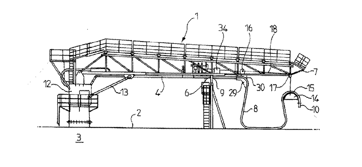
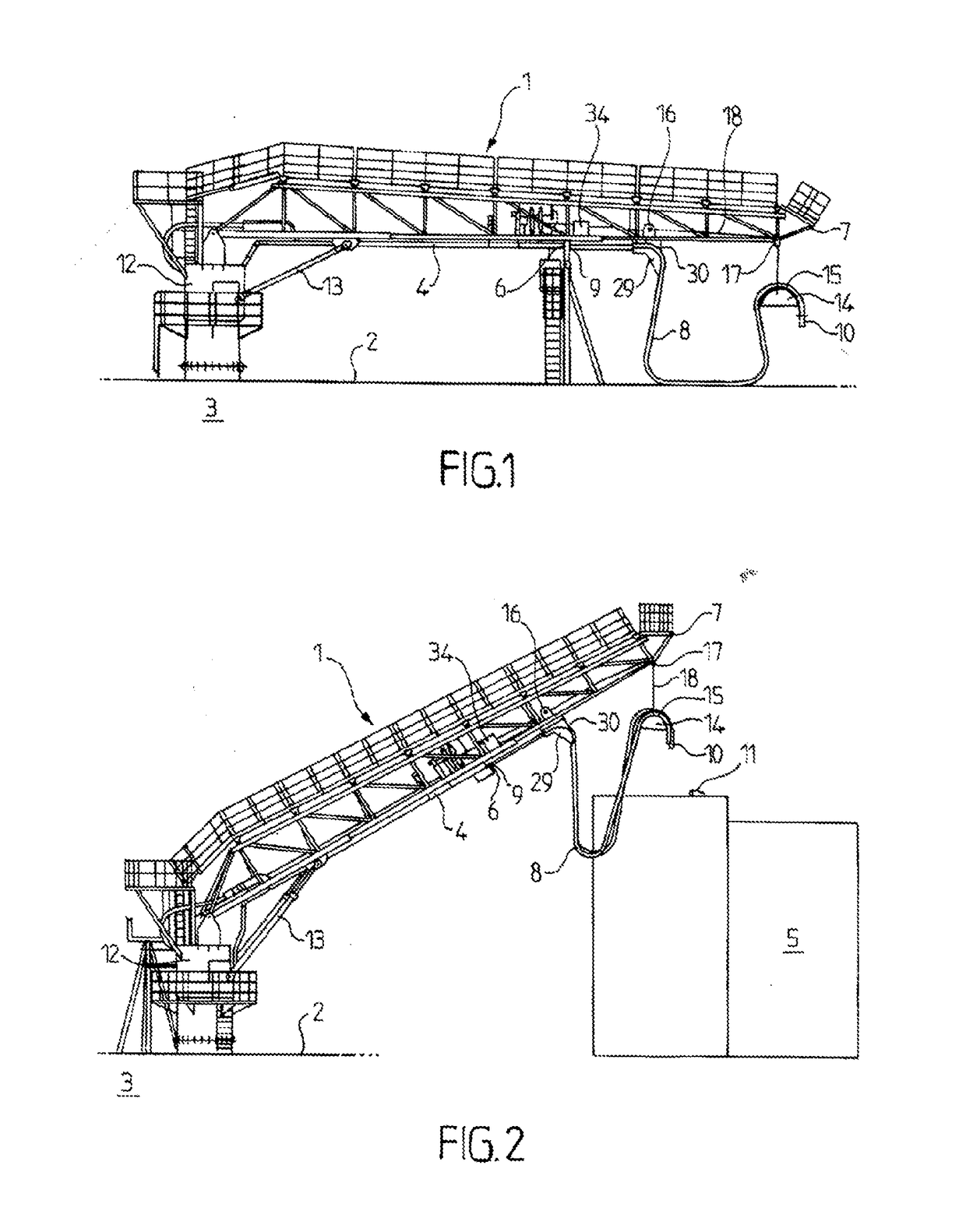
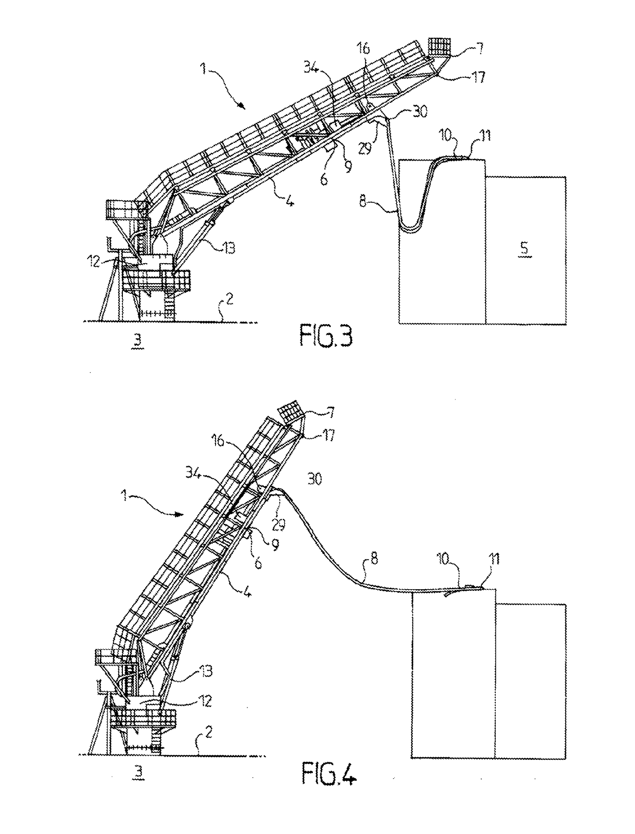
[0062]A transfer system that can be used to transfer a fluid such as liquefied natural gas (LNG) between a supply ship and a facility, such as a client ship, will be described below. The supply ship is for example a bunkering ship responsible for refueling other ships with LNG, and the client ship is a ship propelled by LNG.

[0063]With reference to FIGS. 1 to 6, it will be seen that the transfer system comprises a lattice mast 1 mounted on the deck 2 of supply ship 3. Lattice mast 1 comprises three uprights assembled by a plurality of bracing cross-members extending between the uprights.

[0064]Mast 1 carries a plurality of transfer lines 4 extending along the mast. Transfer lines 4 comprise rigid elements. For example, mast 1 carries three transfer lines 4. Two of transfer lines 4 are connected to a liquefied natural gas storage tank on supply ship 3 and are used to transfer liquefied natural gas from supply ship 3 to the client ship. Third transfer line 4 allows natural gas in the ga...


PUM


Abstract

A system for transferring fluid between a ship and a facility has a mast with a proximal end pivotally mounted on a deck of the ship and a distal end, a fluid-transfer line extending along the mast, a flexible pipe with a first end connected to the fluid-transfer line and a second end connected to a manifold of the facility, the flexible pipe being equipped with a connecting device having an emergency cut-off comprising two elements which are capable of automatically separating in a separation direction, when a separating force which is above a threshold is exerted, and a guide element supported by the mast, and comprising a convex surface for guiding the flexible pipe which is capable of absorbing a pulling force of the flexible pipe such that this force is exerted on the connecting device having an emergency cut-off in the separation direction

Description

TECHNICAL FIELD[0001]The invention relates to the field of fluid transfer and relates more particularly to the transfer of liquefied natural gas between a ship and a facility, such as a client ship.PRIOR ART[0002]Systems for the transfer of liquefied natural gas between two ships at sea are known in the state of the art.[0003]Document WO0134460 discloses a system whereby liquefied natural gas can be transferred between a liquefied natural gas production vessel and a vessel transporting liquefied natural gas. The transfer system comprises three parallel flexible pipes, two of which pipes are used to transfer liquefied natural gas from the production vessel to the transport vessel while the third pipe is used to transfer gas from the transport vessel to the production vessel to balance out the pressures in the gaseous tops of the tanks on both ships and prevent the pressure within the tank on the production vessel from falling. The three flexible pipes are suspended from a mast movabl...

Claims


Application Information

Patent Timeline
Patent Type & Authority Applications(United States)
IPC IPC(8): B63B27/24B63B22/00B67D9/00B63B27/34
CPCB63B27/24B67D9/00B63B22/00B63B27/34B67D9/02B63B25/16
Inventor GELIN, GUILLAUMEENGLEBERT, PATRICK
Owner GAZTRANSPORT & TECHNIGAZ SA
Why Eureka
Try Eureka