
Drawbar pin ejector

a technology of ejector and drawbar pin, which is applied in the field of drawbars, can solve the problems of difficult to remove the drawbar pin from the housing, and the drawbar pin may become stuck, and achieve the effect of facilitating removal

Active Publication Date: 2017-05-04
AGCO CORP
View PDF2 Cites 2 Cited by
  • Summary
  • Abstract
  • Description
  • Claims
  • Application Information

AI Technical Summary

Benefits of technology

The invention is about a mechanism that attaches a drawbar to a towed implement. It includes a locking plate that can be moved to stop or unlock the drawbar. There is also an ejector arm that can be used to remove the drawbar pin. The mechanism is easy to operate and ensures safe and efficient attachment and removal of the drawbar.

Problems solved by technology

While attaching and detaching drawbar pulled implements to a tractor, the drawbar pin may become stuck and be difficult to pull out from its housing.

Method used


Image

  • Drawbar pin ejector
  • Drawbar pin ejector
  • Drawbar pin ejector

Examples


Embodiment Construction

[0023]The invention will now be described in the following detailed description with reference to the drawings, wherein preferred embodiments are described in detail to enable practice of the invention. Although the invention is described with reference to these specific preferred embodiments, it will be understood that the invention is not limited to these preferred embodiments. But to the contrary, the invention includes numerous alternatives, modifications and equivalents as will become apparent from consideration of the following detailed description.

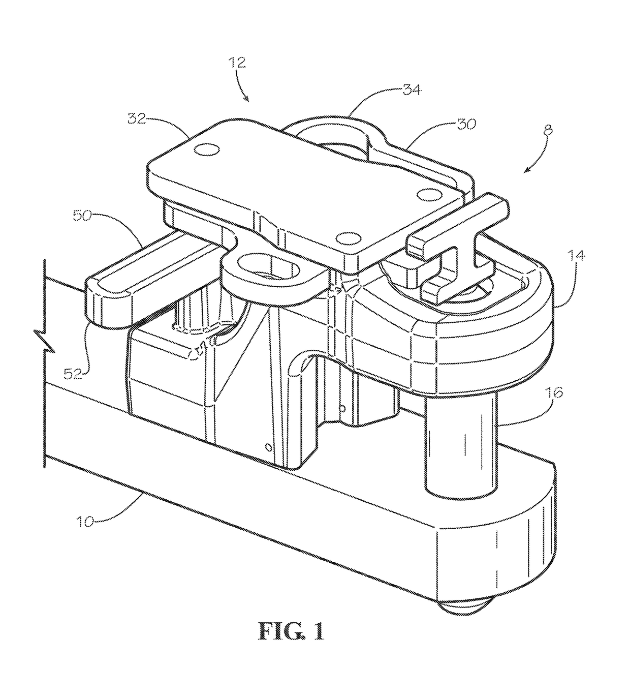
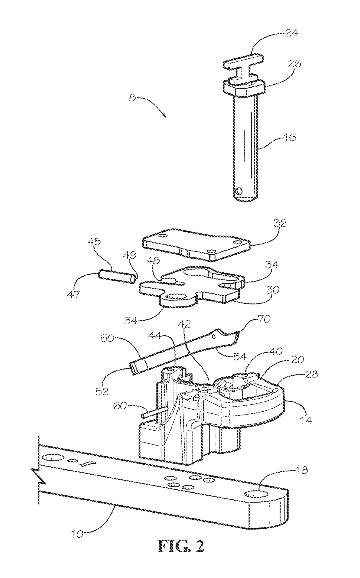
[0024]Turning to the figures wherein like numbers represent like elements throughout the several views, FIG. 1 shows a drawbar assembly 8 including a drawbar 10 and a drawbar pin retention device 12. The drawbar 10 may have a clevis 14 configured to receive a drawbar pin 16. As best seen in the exploded view of FIG. 2, the drawbar 10 and clevis 14 each have a bore 18, 20 respectively through which the drawbar pin 16 may be inserted....


PUM


Abstract

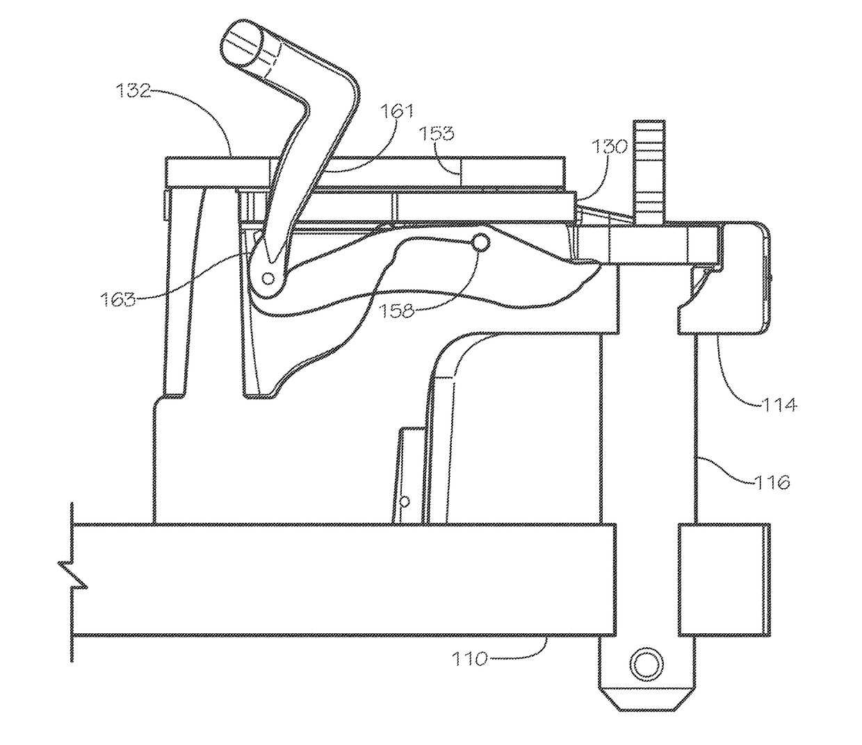
A drawbar assembly for coupling a drawbar to a tongue of a towed implement includes a drawbar pin and a drawbar clevis having a bore configured to receive the drawbar pin. A locking plate is coupled to the drawbar clevis and movable between a pin-lock condition in which the locking plate is configured to obstruct at least a portion of the bore, and a pin-unlock condition. An ejector mechanism is configured to dislodge the drawbar pin from the bore. The ejector mechanism includes a handle utilized to operate the ejector mechanism and an ejector arm pivotably disposed in an ejector recess in the clevis. The ejector arm is movable from a home position in which the ejector arm does not interfere with the drawbar pin to an eject position in which the ejector arm forces the drawbar pin to be at least partially dislodged out of the bore.

Description

CROSS REFERENCE TO RELATED APPLICATION[0001]This application claims the benefit of U.S. Provisional Application No. 62 / 250,616 filed Nov. 4, 2015, which is hereby incorporated by reference in its entirety.BACKGROUND[0002]Field of Invention[0003]The present invention relates generally to drawbars for coupling an implement to a vehicle, and more particularly, to drawbar pin ejector devices.[0004]Description of Related Art[0005]Drawbars are commonly used to couple implements to agricultural vehicles, such as tractors. For example, a drawbar may have a clevis arranged to receive a tongue of an implement to be towed. The clevis and tongue may have bores through which a drawbar pin is inserted to couple the drawbar and tongue together.[0006]While attaching and detaching drawbar pulled implements to a tractor, the drawbar pin may become stuck and be difficult to pull out from its housing. It would be desirable to have a drawbar coupling system that partially ejects the drawbar pin from the...

Claims


Application Information

Patent Timeline
Patent Type & Authority Applications(United States)
IPC IPC(8): B60D1/02B60D1/28
CPCB60D1/28B60D1/025B60D1/02
Inventor HRUSKA, DEREKSHAW, MATTHEW
Owner AGCO CORP
Learn More