Manifold assembly

a manifold and assembly technology, applied in the field of engine components, can solve the problems of lowering the air-fuel ratio, tremor of the vehicle, and inaccurate data detection,

Active Publication Date: 2018-02-22
GM GLOBAL TECH OPERATIONS LLC
View PDF5 Cites 3 Cited by
  • Summary
  • Abstract
  • Description
  • Claims
  • Application Information

AI Technical Summary

Problems solved by technology

However, the conventional air flow sensor has time error from detecting to sensing so that the detecting data is not accurate.
Moreover, a time error will also be occurred when the air flows in, thereby lowering air-fuel ratio.
When the accelerator pedal is pressed to increase the vehicle speed, the vehicle may tremble or the vehicle will be stuck.
Furthermore, in an environment having thin air, the amount of the air flow is not enough, therefore air-fuel ratio is low, and thus the power of the inner combustion engine is low, thereby lowering the climbing ability of the vehicle.
Moreover, hot air also causes a higher cylinder temperature which can aid in pre-detonation of the combustion cycle which results in inefficient engine operations.
The use of several intermediate components which attach on one side to the engine cover and on the other side to an en...

Method used


Image

  • Manifold assembly
  • Manifold assembly
  • Manifold assembly

Examples


Embodiment Construction

[0019]The exemplary embodiments described herein provide detail for illustrative purposes, and are subject to many variations in composition, structure, and design. It is understood that various omissions and substitutions of equivalents are contemplated as circumstances may suggest or render expedient, but these are intended to cover the application or implementation without departing from the spirit or scope of the claims of the present disclosure. Also, it is to be understood that the phraseology and terminology used herein are for the purpose of description and should not be regarded as limiting.

[0020]The terms “first,”“second,” and the like, herein do not denote any order, quantity, or importance, but rather are used to distinguish one element from another, and the terms “a” and “an” herein do not denote a limitation of quantity, but rather denote the presence of at least one of the referenced items.

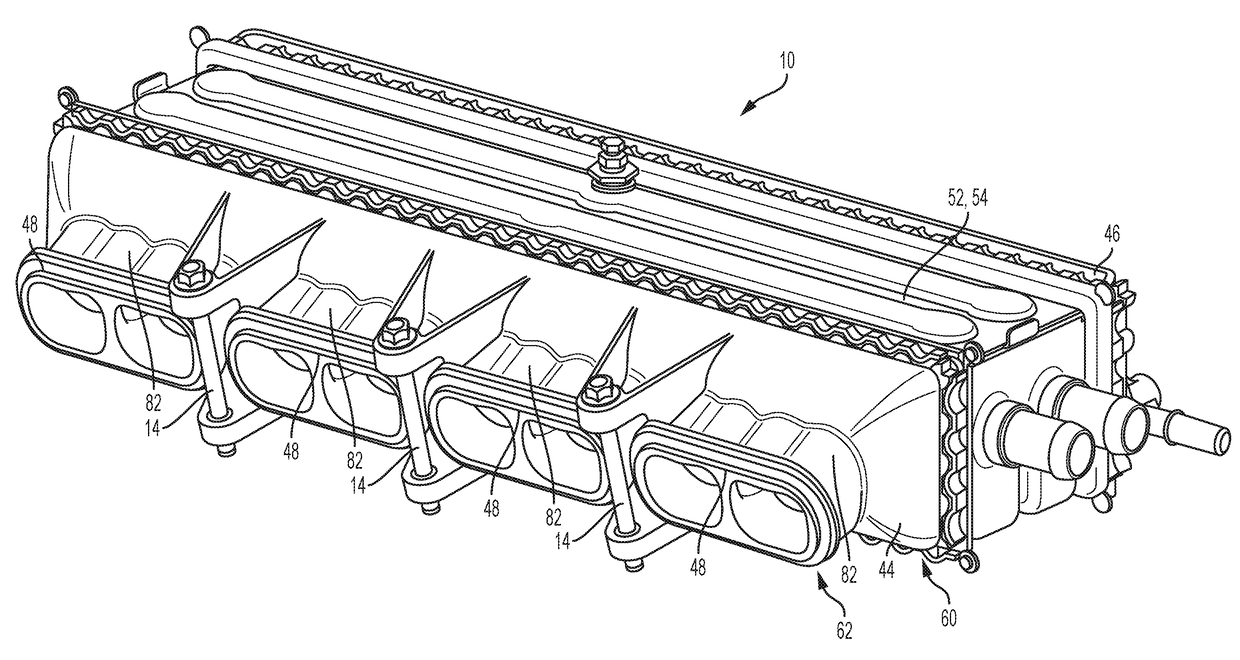
[0021]The present disclosure provides for a manifold assembly 10. The manifold ...


PUM


Abstract

A manifold assembly includes a clevis-style mounting structure, a first manifold section, a second manifold section, an accessory disposed between the first and second manifold sections, and a plurality of threaded clevis fasteners. The clevis-style mounting structure includes an upper clevis structure and a lower threaded clevis structure. The clevis-style mounting structure may be operatively configured to be mounted on a cylinder head. The first manifold section has distal and proximal ends. The first manifold section is integral to the clevis style mounting structure. The plurality of threaded clevis fasteners operatively configured to mount the clevis-style mounting structure to a cylinder head via a plurality of corresponding passageways defined in the cylinder head.

Description

TECHNICAL FIELD[0001]The present disclosure relates to engines, engine components, and more particularly, an intake manifold assembly.BACKGROUND[0002]An internal combustion engine is used to transfer the fuel (e.g. air and gasoline) to mechanical energy to operate an engine. A complete process of transferring the fuel to mechanical energy is called engine cycle. The operation of the engine commonly includes a plurality of engine cycles.[0003]An engine cycle generally includes four strokes: intake, compression, power transformation and exhaust. Intake is for generating vacuum by the pressure difference to the atmosphere. Air is filtered, and the filtered air is pulled in by the vacuum; then the filtered air is mixed with a gasoline jetted by a nozzle in a cylinder block. Compression is for compressing; the mixed gasoline in the cylinder block. Power transformation is for burning the mixed gasoline to expand the volume thereof, thereby pushing the piston to generate mechanical energy....

Claims


Application Information

Patent Timeline
IPC IPC(8): F02M35/104F02M35/10
CPCF02M35/104F02M35/10268F02M35/10321F02M35/10006F02M35/10085F02M35/10157F02M35/112F02M35/10078F02M35/10144
Inventor OWEN, SHAWN W.SPEROW, TRAVIS
Owner GM GLOBAL TECH OPERATIONS LLC
Why Eureka
Try Eureka