Oil separator combined with cylinder head cover

Inactive Publication Date: 2005-05-05
MAHLE FILTER SYST JAPAN CORP
View PDF9 Cites 52 Cited by
  • Summary
  • Abstract
  • Description
  • Claims
  • Application Information

AI Technical Summary

Benefits of technology

[0005] It is, therefore, an object of the present invention is to provide an improved oil separator provided in combination with a cylinder head cover of an int

Problems solved by technology

Accordingly, oil droplets separated are spread on the upper surface of the inner plate ther

Method used


Image

  • Oil separator combined with cylinder head cover
  • Oil separator combined with cylinder head cover
  • Oil separator combined with cylinder head cover

Examples


Embodiment Construction

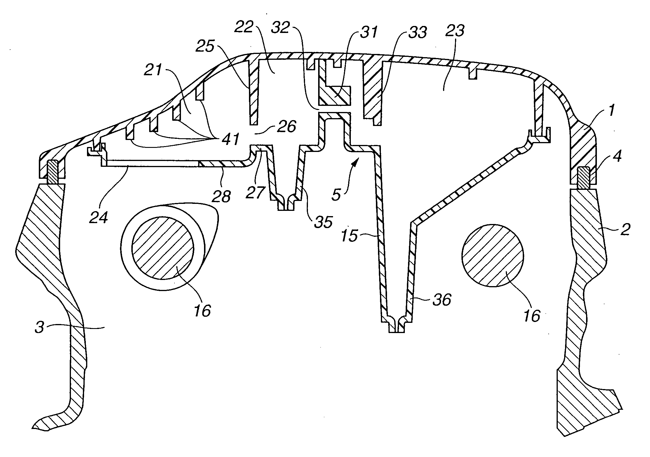
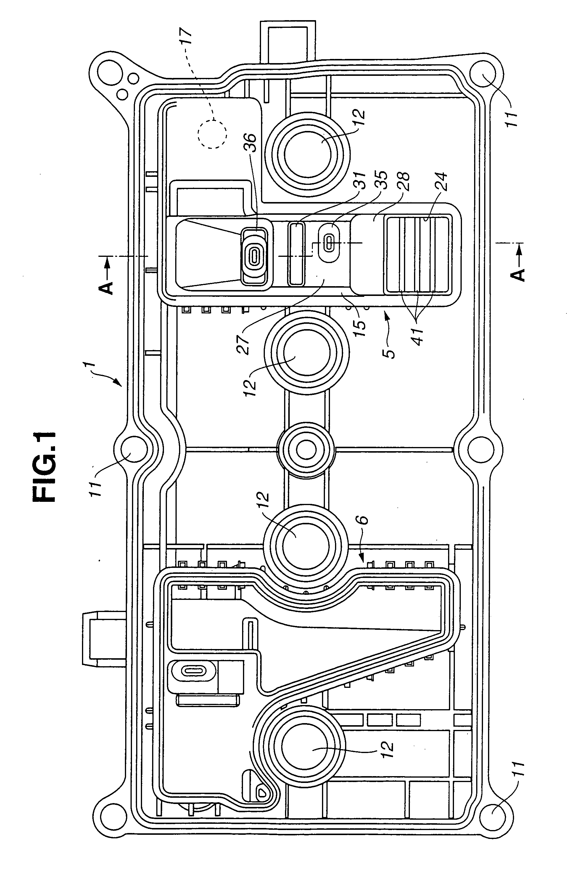
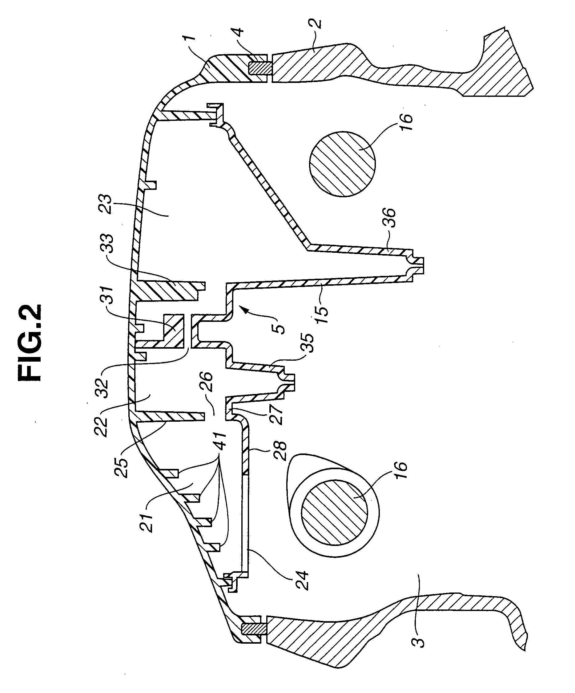
[0015] Referring now to FIGS. 1 and 2, an embodiment of an oil separator according to the present invention is illustrated to be provided in combination with a cylinder head cover 1 of an internal combustion engine. The internal combustion engine is of the in-line 4-cylinder type. FIG. 1 shows an inside arrangement of the cylinder head cover 1. This cylinder head cover 1 is installed together with a seal member 4 on a cylinder head 2 of the internal combustion engine as shown in FIG. 2, and defines a valve operating chamber 3 for accommodating a valve operating mechanism (not shown) of a so-called DOHC type. The valve operating chamber 3 is in communication with a crankcase of the side of a cylinder block (not shown). Blow-by gas flows from the crankcase to the valve operating chamber 3 and then is guided to the outside of the engine through a blow-by gas passage (not shown) connected to the cylinder head cover 1.

[0016] The cylinder head cover 1 is formed of plastic such as polyami...


PUM


Abstract

An oil separator provided in combination with a cylinder head cover of an internal combustion engine. The oil separator includes a separator cover fixed to an inner surface of the cylinder head cover defining a space extending in a first direction perpendicular to axis of a camshaft in plan, between the separator cover and the cylinder head cover. The separator cover has an opening through which the space is opened to a valve operating chamber. A partition wall is provided to define in the space an inlet-side separator chamber and an outlet-side separator. The partition wall extends in a second direction parallel with the axis of the camshaft and being formed with a plurality of fine passages. Additionally, a plurality of projection walls project from a part of the inner surface of the cylinder head cover which faces the valve operating chamber through the opening.

Description

BACKGROUND OF THE INVENTION [0001] This invention relates to improvements in an oil separator provided in combination with a cylinder head cover of an internal combustion engine to separate oil mist in blow-by gas to be discharged out of the engine through the cylinder head cover. [0002] As is well known, in an internal combustion engine of an automotive vehicle, blow-by gas containing unburnt gas component leaked into a crankcase from combustion chambers of the engine is again introduced or recirculated into the combustion chambers through an engine air intake system, together with fresh taken in from the outside of the engine. In such recirculation of blow-by gas, blow-by gas flowing through the crankcase contains oil mist of lubricating oil. In order to prevent oil mist from being carried to the engine intake system, in general, an oil separator is provided in combination of a cylinder head cover as a single unit so that the blow-by gas is taken out from the engine after oil mist...

Claims


Application Information

Patent Timeline
IPC IPC(8): F01M13/04F02F7/00
CPCF01M13/0416
Inventor NONAKA, ATSUSHIMOCHIZUKI, TERUMOTO
Owner MAHLE FILTER SYST JAPAN CORP
Why Eureka
Try Eureka