Power steering system

a technology of power steering and steering wheel, which is applied in the direction of mechanical equipment, servomotors, transportation and packaging, etc., can solve the problems of unavoidably easy movement operation delay of hydraulic power cylinders, and steering tends to become unstable, so as to overcome drawbacks effectively

Inactive Publication Date: 2005-05-03
HITACHI LTD
View PDF7 Cites 13 Cited by
  • Summary
  • Abstract
  • Description
  • Claims
  • Application Information

AI Technical Summary

Benefits of technology

[0005]It is an object of the present invention to provide an improved power steering system

Problems solved by technology

However, in the above conventional power steering system, the internal pressure of the hydraulic circuit for connecting the left-side and right-side hydraulic pressure chambers of the hydraulic power cylinder becomes a level of generally atmospheric pressure during non-steering assisting in which an oil pump is not operated, and therefore the hydraulic power cylinder is unavoidably readily moved when kickback is input to the hydraulic power cylinder from road surface so that steering tends to become unstable.
Additionally, since the pressure within the hydraulic circuit becomes the level of generally atmospheric pressure during the non-steering assisting, a time is required until the hydraulic pressure within the hydr

Method used


Image

  • Power steering system
  • Power steering system
  • Power steering system

Examples


first embodiment

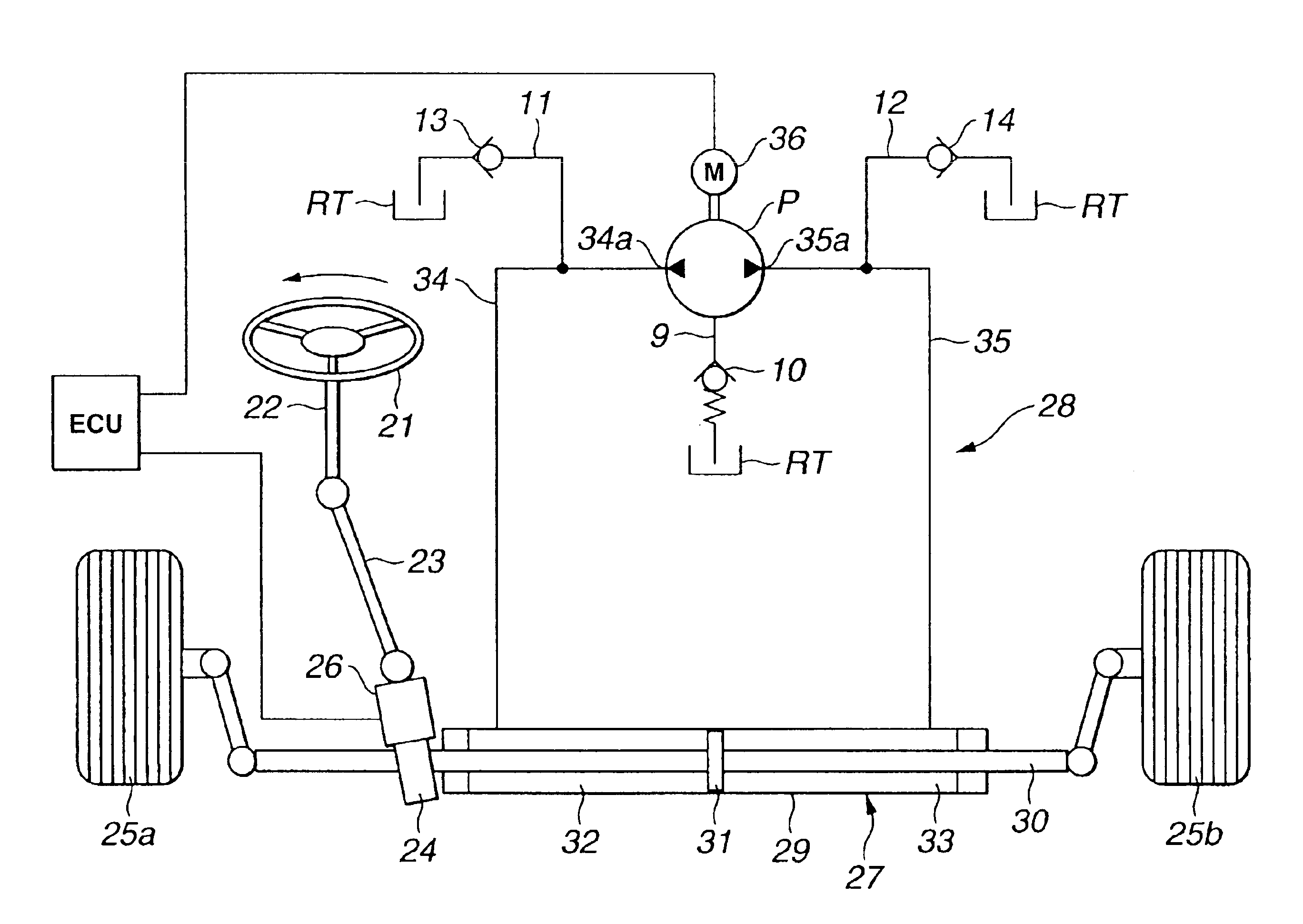
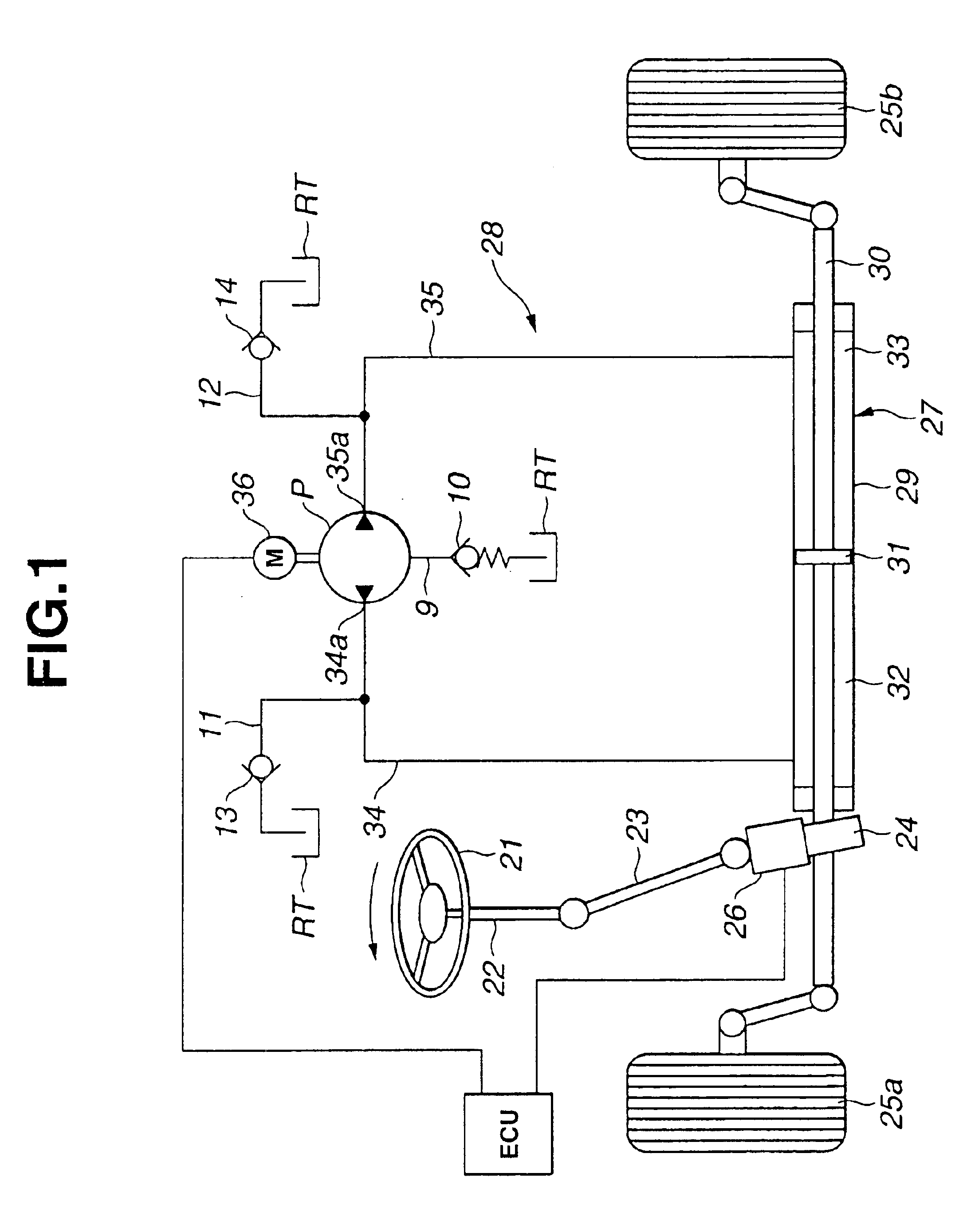
[0025]Referring now to FIG. 1 of the drawings, a power steering system according to the present invention is illustrated. The power steering system comprises a steering shaft 22 on which a steering wheel 21 is fixedly mounted as a steering effort input means. An output shaft 23 is connected to the lower end portion of steering shaft 22. A rack and pinion steering gear 24 is connected to the lower end portion of the output shaft 23 and forms part of a steering mechanism. A steering effort sensor 26 is provided at the lower end side of output shaft 23 to detect a rotational direction of steering shaft 22 and a steering effort applied to steering shaft 22. A hydraulic power cylinder 27 is connected to rack and pinion steering gear 24. A hydraulic circuit 28 is provided to supply a hydraulic pressure to hydraulic power cylinder 27.

[0026]Hydraulic power cylinder 27 includes a cylinder section 29 which extends in the direction of width of a vehicle body. A piston rod 30 is disposed in cyl...

fourth embodiment

[0056]Operation of the fourth embodiment power steering control system will be discussed together with advantageous effects of the present invention.

[0057]Since the fourth embodiment of the power steering control system is arranged as discussed above, when the driver leftward turns steering wheel 21 as indicated by an arrows in FIG. 6, the control unit ECU outputs the control signal, for example, to control electric motor 36 to rightly rotate, so that the reversible pump P is driven to rightly rotate. Under the action of the thus rotating pump, a part of the hydraulic fluid discharged to the first hydraulic line 34 flows through first introduction passage 50 into pressure receiving chamber 47c. This part is higher in hydraulic pressure than the hydraulic fluid passed through the first pressure control valve 39 thereby to develop a pressure differential, and therefore valve body 47a of first poppet valve 47 is pushed rightward against the biasing force of spring 47j under the pressur...

fifth embodiment

[0066]Hereinafter, the power steering system according to the present invention will be discussed with reference to FIG. 7.

[0067]In this embodiment, the power steering system comprises a steering shaft 102 on which a steering wheel 101 is fixedly mounted as a steering effort input means. A rack and pinion steering gear 103 is connected to the lower end portion of steering shaft 102 and forms part of a steering mechanism. A detector 104 is provided at the lower end side of steering shaft 102 to detect a torque input to steering wheel 101 and a road surface input from road wheels (not shown). The detector 104 is adapted to output detection signals representative of the torque and the road surface input. A hydraulic power cylinder 105 is connected to rack and pinion steering gear 103. The hydraulic power cylinder 105 is connected to a main part of a hydraulic circuit 106 through which hydraulic fluid is supplied to or discharged from hydraulic power cylinder 105 in accordance with the ...


PUM


Abstract

A power steering system for a vehicle, comprises a steering shaft connected to a steering mechanism. A hydraulic power cylinder is provided for assisting a steering effort of the steering mechanism. A reversible pump is provided having first and second discharge ports which are respectively connected through first and second hydraulic lines with two hydraulic pressure chambers of the hydraulic power cylinder so that the two hydraulic pressure chambers are respectively provided with hydraulic pressures. A driving device is provided for driving the reversible pump to rightly and reversely rotate. A differential pressure regulating valve is disposed in the hydraulic circuit to maintain pressure at least in the first and second hydraulic lines at a level of atmospheric pressure or higher in an inoperative condition of the reversible pump.

Description

BACKGROUND OF THE INVENTION[0001]This invention relates to improvements in a power steering system, and more particularly to the power steering system in which a steering assist force is developed by a hydraulic power cylinder.[0002]A power steering system of the kind wherein a steering assist force is developed by a hydraulic power cylinder is disclosed in Japanese Patent Provisional Publication No. 2001-1918. This power steering system includes hydraulic lines (44a, 44b) which are connected respectively with left-side and right-side hydraulic pressure chambers of the hydraulic power cylinder. Relief valves (54a, 54b) are disposed respectively in hydraulic lines. These relief valves are adapted to allow hydraulic fluid to bypass the hydraulic line so as to direct the hydraulic fluid to another oil passage when the internal pressure of a hydraulic circuit becomes a certain level or higher, thereby preventing the hydraulic circuit from becoming into an overload condition.[0003]Howeve...

Claims


Application Information

Patent Timeline
IPC IPC(8): B62D5/06B62D5/065F15B7/00
CPCB62D5/06B62D5/062F15B7/006B62D5/065F15B2211/3051F15B2211/20561
Inventor YOKOTA, TADAHARUKURATA, MASAKAZUHIRAMOTO, MICHIYASUDO, YUKIO
Owner HITACHI LTD
Why Eureka
Try Eureka