Fuel lid apparatus

Active Publication Date: 2005-10-20
MITSUI KINZOKU ACT
View PDF1 Cites 12 Cited by
  • Summary
  • Abstract
  • Description
  • Claims
  • Application Information

AI Technical Summary

Benefits of technology

[0006] Therefore, an object of the present invention is to provide an improved fuel lid appar

Problems solved by technology

Hence, there is a fear that an excessive force acts on the push rod, the link and the cable thereby to deform them.
However, drawbacks have been encountered in the above conventional fuel lid apparatus of Japanese Patent Provisional Publication No. 2001-241239.
Specifically, although the excessive force can be released by the relative rotation of the first and second links, the number of component parts is unavoidably increase

Method used


Image

  • Fuel lid apparatus
  • Fuel lid apparatus
  • Fuel lid apparatus

Examples


Embodiment Construction

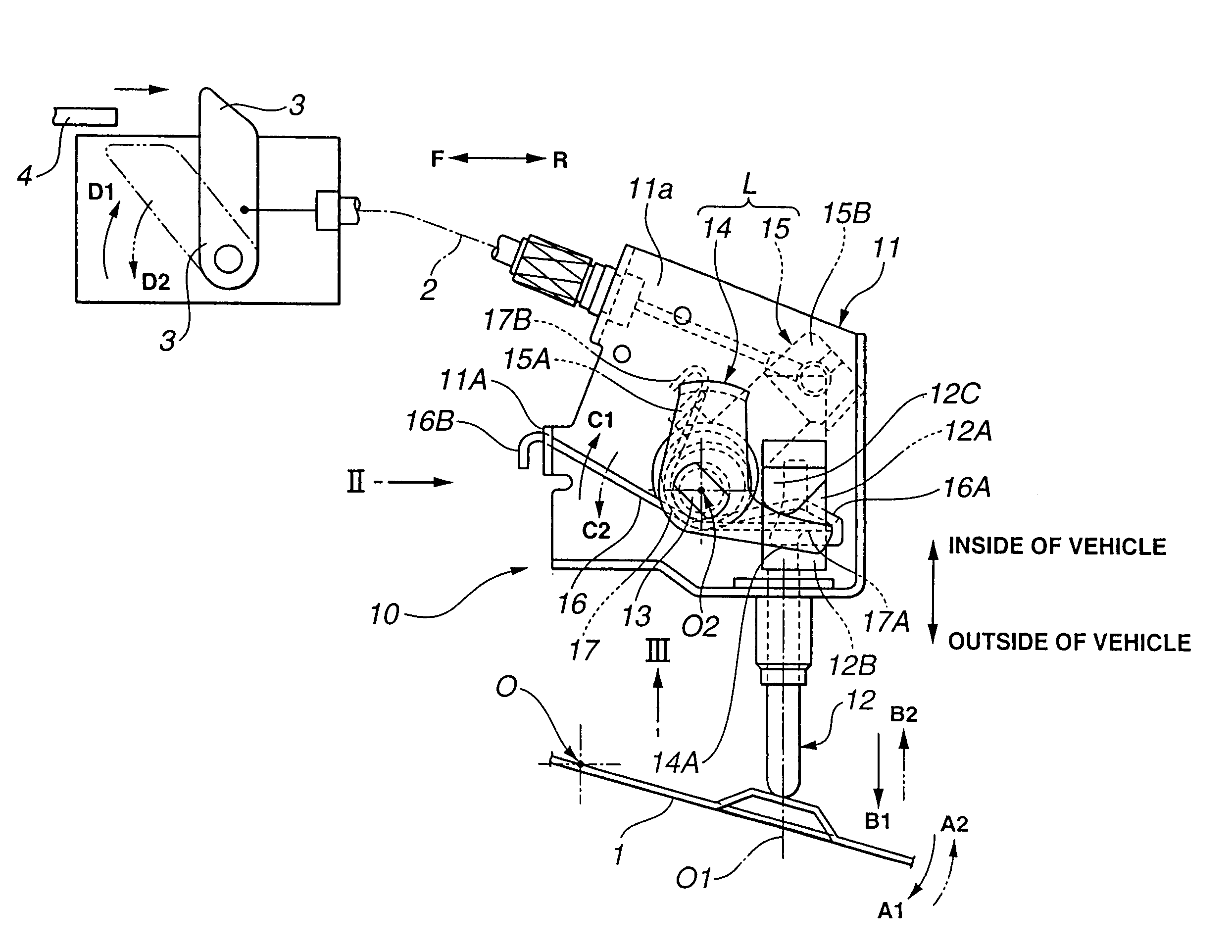
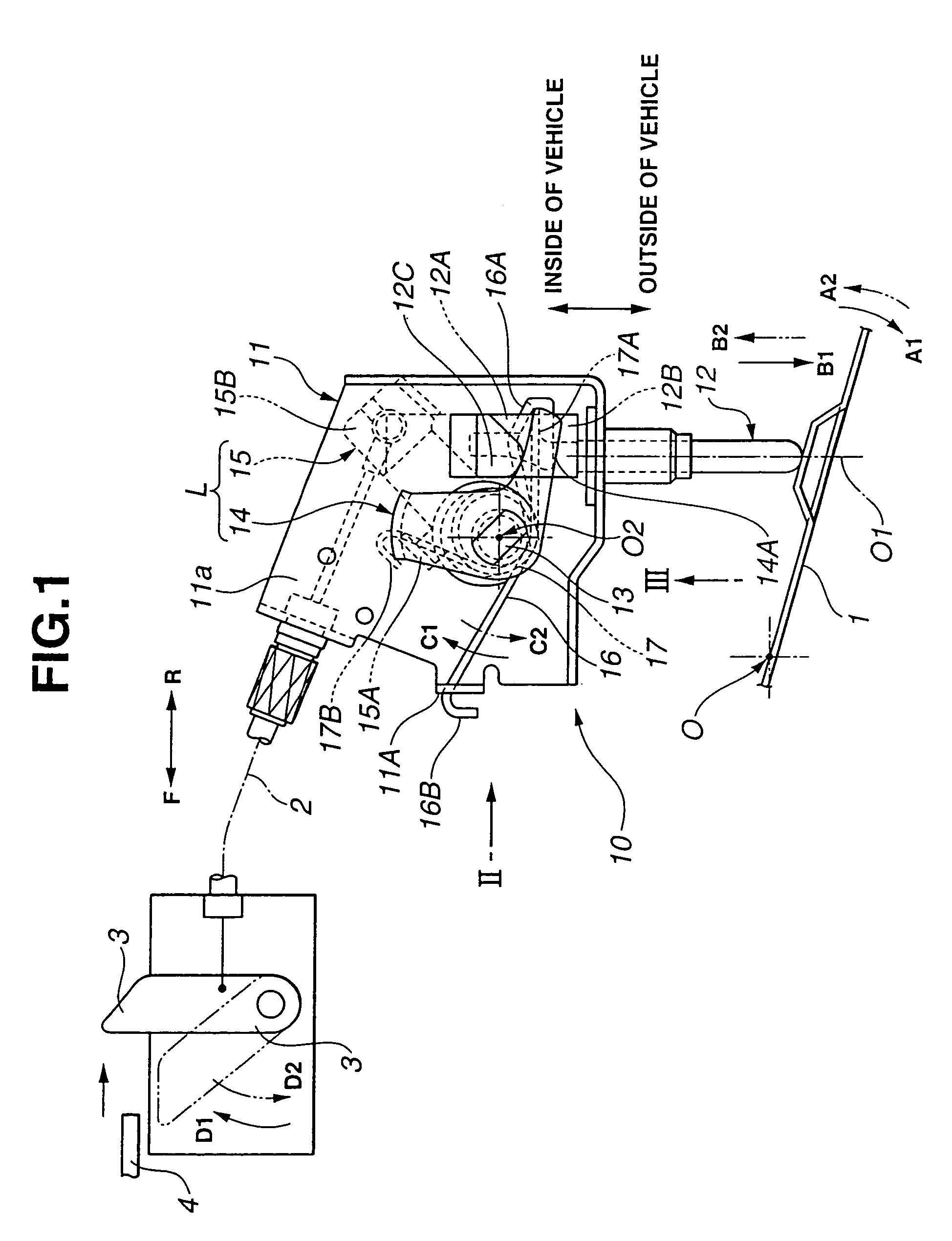
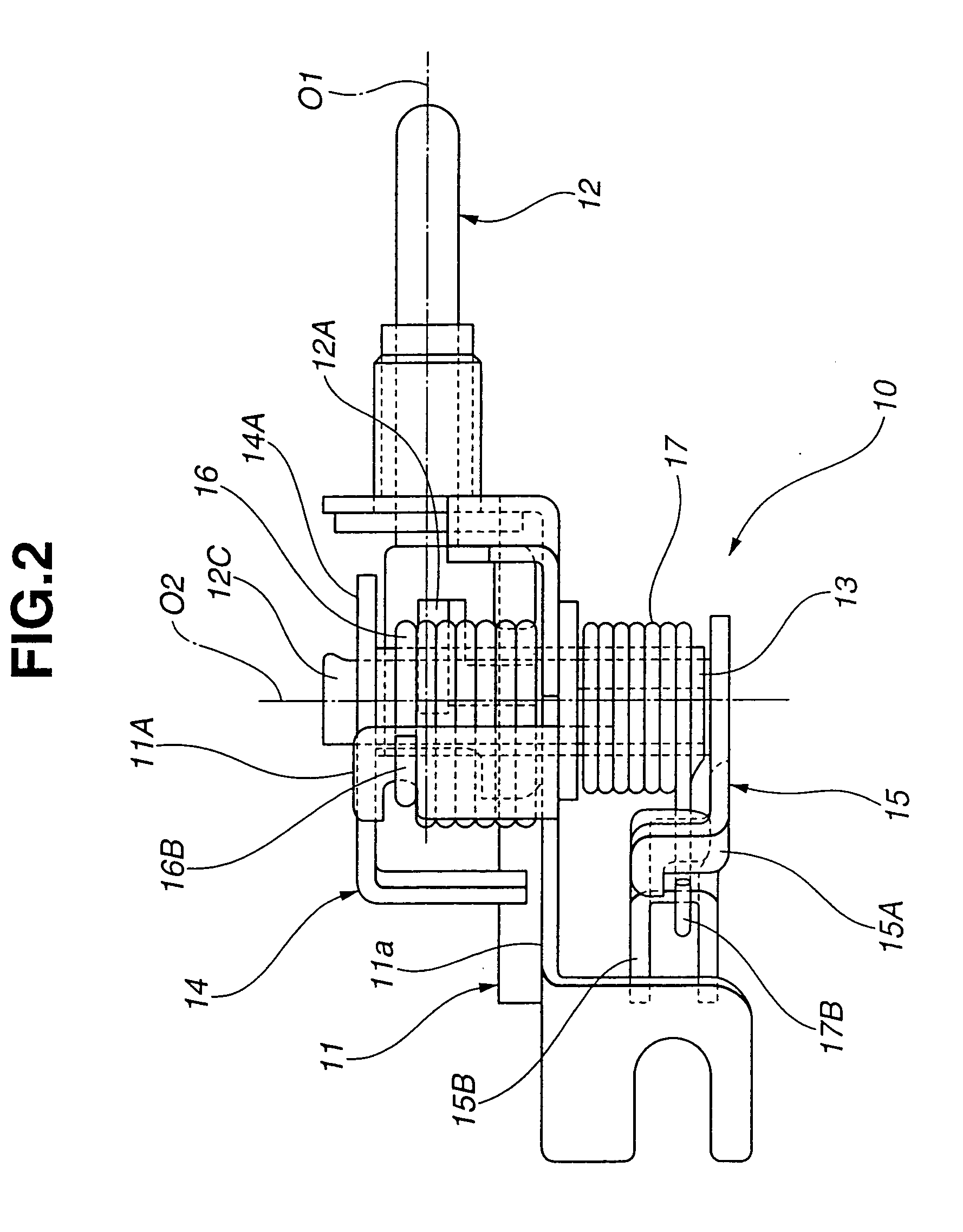
[0019] Referring now to FIGS. 1 to 3 of the accompanying drawings, an embodiment of a fuel lid apparatus according to the present invention is illustrated by the reference numeral 10. FIG. 1 is a side view of the fuel lid apparatus 10 according to the present invention. FIG. 2 is an enlarged side view as viewed from the direction of an arrow II in FIG. 1. FIG. 3 is an enlarged side view as viewed from the direction of an arrow III in FIG. 1. Reference characters “F” and “R” denote a front side and a rear side of a vehicle, respectively. The fuel lid apparatus 10 of the present invention is for an automotive vehicle and installed rear of a slide door at a left side of the vehicle body. The fuel lid apparatus 10 includes a bracket 11 which serves as a base member of a main body of the fuel lid apparatus 10 and is mounted at a certain site on the left side of the vehicle body. A push rod 12 is movably installed to the bracket 11 so as to move along its axis O1 extending vertically in F...


PUM


Abstract

A fuel lid apparatus for an automotive vehicle having a slide door. The fuel lid apparatus includes a push rod displaceable in a first direction by opening a fuel lid under the action of the first biasing device and in a second direction by closing the fuel lid. A link is connected to a stopper for the slide door and capable of moving the stopper to an engaging position by being rotationally moved in a third direction and to a non-engaging position by being rotationally moved in a fourth direction under the action of a second biasing device. In the fuel lid apparatus, the push rod and the second biasing device are in a locational relationship to increase a component force of a biasing force of the second biasing device in the first direction as the push rod is displaced in the first direction.

Description

BACKGROUND OF THE INVENTION [0001] This invention relates to improvements in a fuel lid apparatus for use in an automotive vehicle having a slide door. [0002] In such a fuel lid apparatus used in an automotive vehicle that a fuel lid is placed within a sliding region of a slide door, generally a stopper for the slide door is operated according to the opening and closing actions of the fuel lid. The stopper for the slide door is constructed to allow the slide door to selectively move between an engaging position at which the stopper comes into engagement with the slide door so that the slide door is kept at a partly or half opened position and a non-engaging position at which the stopper does not come into engagement with the slide door so that the slide door can not be kept at the partly or half opened position. When the fuel lid is opened during fuel supply, the fuel lid apparatus moves the stopper to the engaging position so that the slide door can open to the partly or half opene...

Claims


Application Information

Patent Timeline
IPC IPC(8): B60K15/05B60J5/06B62D25/00
CPCB60K2015/0523B60K15/05
Inventor SETO, NAOYA
Owner MITSUI KINZOKU ACT
Why Eureka
Try Eureka