Seat reclining apparatus for automotive vehicle

a seat reclining and automotive technology, applied in the field of vehicle seat reclining apparatus improvement, can solve the problems of inability to improve and stabilize the seat reclining apparatus, drawbacks of the above conventional seat reclining apparatus, etc., and achieve the effect of preventing its breakag

Active Publication Date: 2006-12-05
TF METAL CO LTD
View PDF10 Cites 15 Cited by
  • Summary
  • Abstract
  • Description
  • Claims
  • Application Information

AI Technical Summary

Benefits of technology

[0008]In view of the above, an object of the present invention is to provide an improved seat reclining apparatus for a vehicle which apparatus can effectively overcome drawbacks encountered in conventional seat reclining apparatus.
[0010]According to the present invention, when the lock tooth is displaced toward one of guide sections, a protruding section of the lock tooth is brought into contact with a step portion of the one of the guide sections so as to receive a load. At this time, a reactive force which the protruding section receives from the step portion is directed to the side of the cam with respect to a tangential plane to the bearing surface of the lock tooth, the tangential plane passing the step portion, so that the lock tooth cannot receive the bending stress so as to be prevented from its breakage.

Problems solved by technology

However, drawbacks have been encountered in the above conventional seat reclining apparatus.
More specifically, there is a limit for receiving a load in a case where a further high load is applied to the seat back, so that it is necessary to increase a load applied to the guide section.
However, when the load applied to the guide section increases, there rises a fear that the bending stress acts on the bearing portion of the lock tooth so as to break the lock tooth at an early stage.
That is, the seat reclining apparatus cannot be improved and stabilized in strength.

Method used


Image

  • Seat reclining apparatus for automotive vehicle
  • Seat reclining apparatus for automotive vehicle
  • Seat reclining apparatus for automotive vehicle

Examples


Embodiment Construction

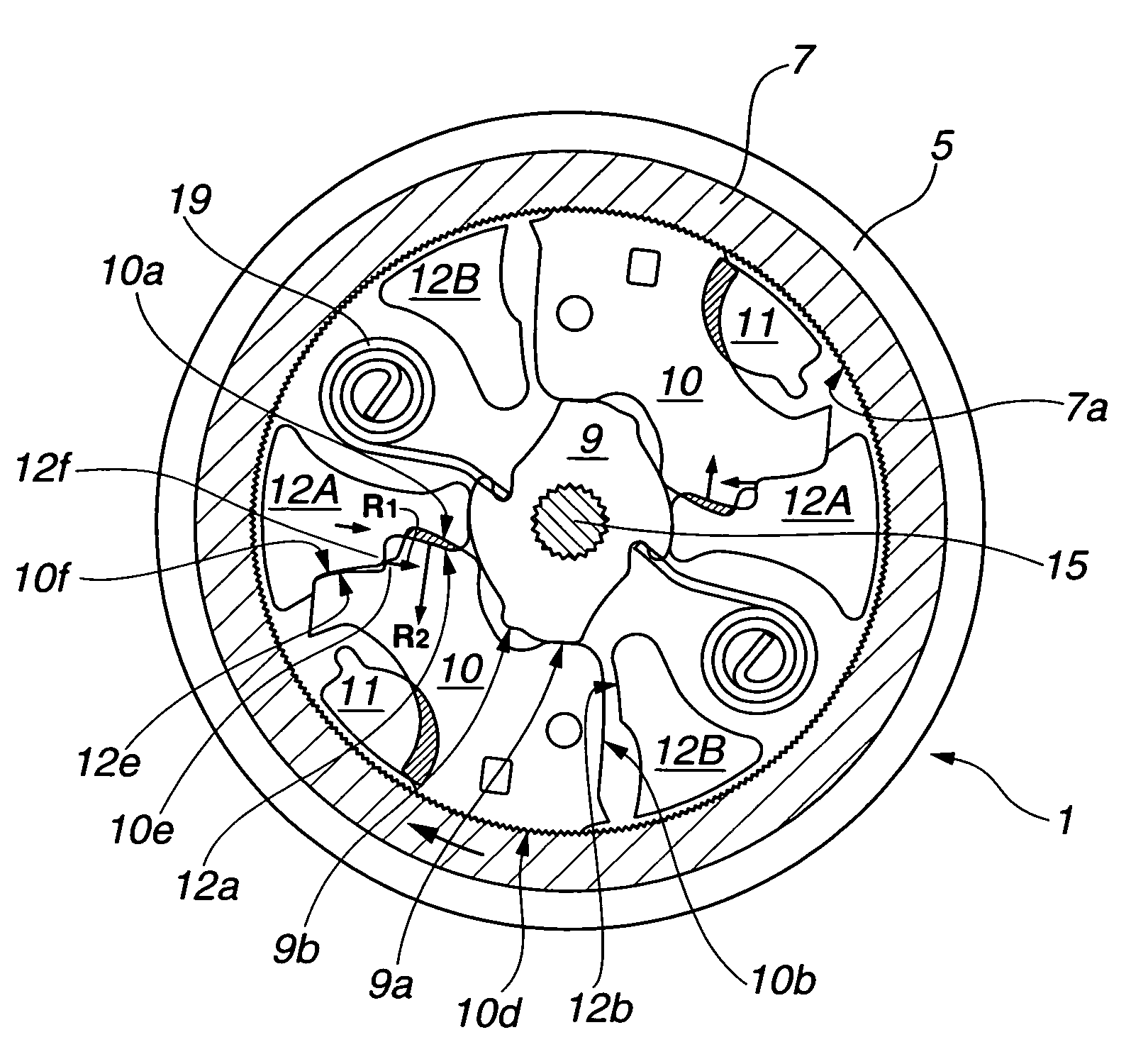
[0018]Referring now to the accompanying drawings, an embodiment of a seat reclining apparatus for a vehicle, according to the present invention is illustrated by reference numeral 1.

[0019]As shown in FIG. 6, a vehicle seat (non numeral) includes a seat cushion 2 on which a vehicle occupant is to be seated. A seat back 3 is fixed rotatable relative to the seat cushion 2 in such a manner as to rotationally incline in a fore-and-aft direction of a vehicle. A frame or base member 5 is connected to the seat cushion 2 through a base plate 4. A lid member or rotational member 7 which is not illustrated is connected to the seat back 3 through an arm plate 6. Additionally, a spring is disposed to bias the seat back 3 in a direction to fall leftward in FIG. 6, though not shown. The left side in FIG. 6 corresponds to the front side of the vehicle.

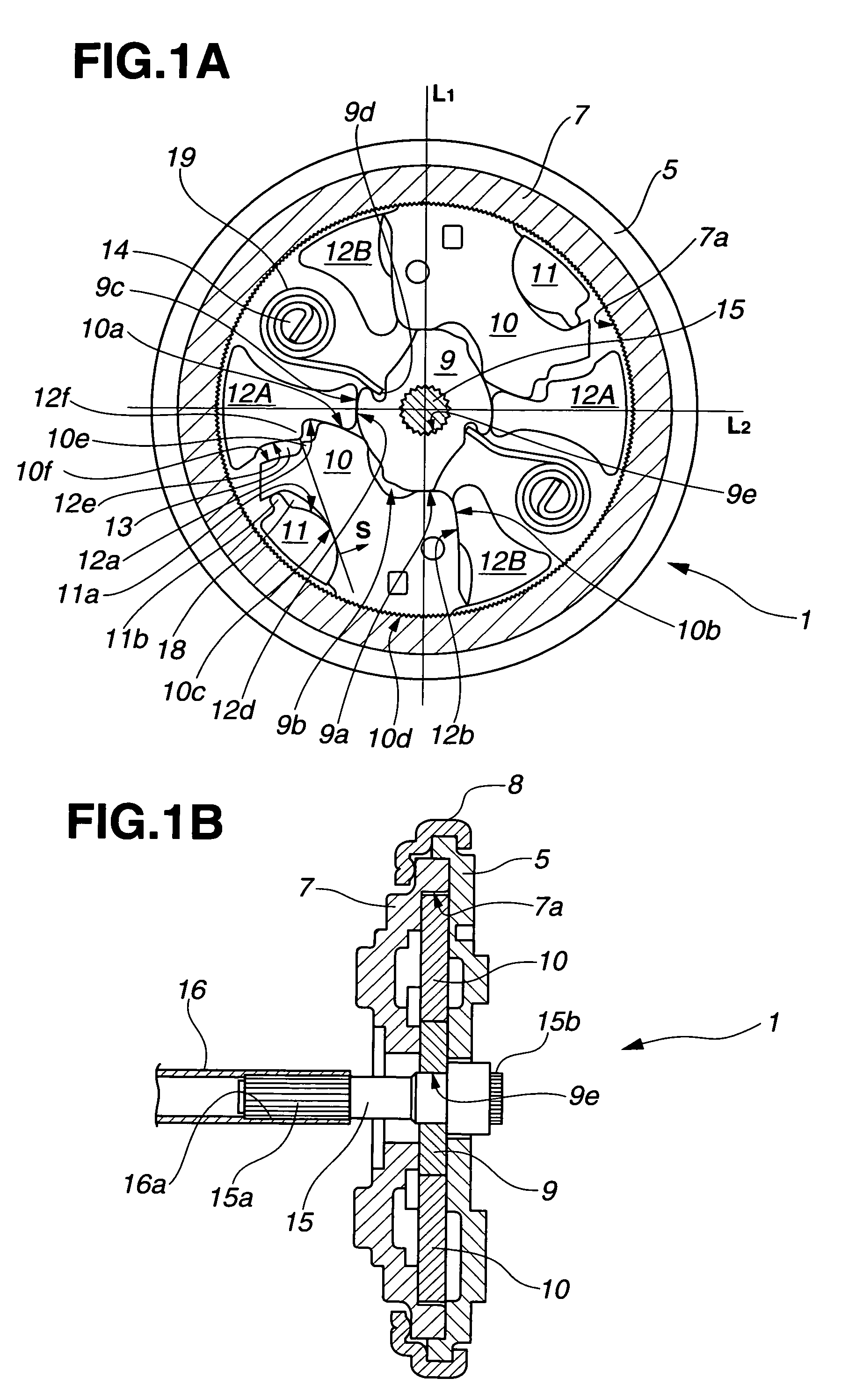
[0020]As illustrated in FIGS. 1A and 1B, the seat reclining apparatus 1 for the vehicle will be discussed in detail. The above frame 5 and the above ...


PUM


Abstract

A seat reclining apparatus for a vehicle including a base member and a rotational member having an internal gear. A lock tooth is provided having an external gear engageable with the internal gear. A shaft section is provided is provided having an outer peripheral side guide surface. A cam is provided for having an inner peripheral side guide surface. Each of a pair of guide sections biasing the lock tooth to engage the external gear with the internal gear. The lock tooth has an outer peripheral side slide surface and a contact face. One of the guide sections has a backup surface. The one of the guide sections has a step portion formed between the outer peripheral side guide surface and the backup surface. Further, the lock tooth has a protruding section contactable with the step portion.

Description

BACKGROUND OF THE INVENTION[0001]This invention relates to improvements in a seat reclining apparatus for a vehicle which apparatus is arranged to angularly adjustably fix a seat back serving as a backrest to a seat cushion on which a vehicle occupant is seated so as to be sustainable even when an excessive load is applied to the seat back.[0002]A seat reclining apparatus for a vehicle is provided to a vehicle seat to angularly adjustably fix a seat back to a seat cushion, by which a position of the seat back can be angularly adjusted with respect to the seat cushion. A conventional seat reclining apparatus includes, for example, a frame installed to a base plate on the side of the seat cushion, and a lid member installed to an arm plate on the side of the seat back. The frame and the lid member are arranged rotatable to each other. An external gear of a lock tooth installed to the frame is engaged with an internal gear formed at the inner peripheral surface of the lid member so as ...

Claims


Application Information

Patent Timeline
Patent Type & Authority Patents(United States)
IPC IPC(8): B60N2/235
CPCB60N2/2356B60N2/2362A45D2/08A45D2/10A45D4/06A45D2200/15
Inventor OHBA, TETSUYA
Owner TF METAL CO LTD
Why Eureka
Try Eureka