Cylinder device

a cylinder device and cylinder technology, applied in the direction of engines without rotary main shafts, machines/engines, manufacturing tools, etc., can solve the problems of large design restrictions, unavoidable increase in the length considerable restriction in the design of the cylinder device, so as to achieve the effect of overcoming drawbacks

Inactive Publication Date: 2005-01-04
HITACHI ASTEMO LTD
View PDF6 Cites 12 Cited by
  • Summary
  • Abstract
  • Description
  • Claims
  • Application Information

AI Technical Summary

Benefits of technology

It is, therefore, an object of the present invention to provide an improved cylinder device which can effectively overcome drawbacks encountered in conventional cylinder devices such as a power cylinder of a power steering system.

Problems solved by technology

However, in the above conventional cylinder device, the stopper member is incorporated and fixed in the state where the inner peripheral section of the metal ring is put between the end face of the rack bar and the end face of the socket at the screw-in joint as discussed above, and therefore the length of the cylinder device is unavoidably increased by an amount corresponding to the thickness of the metal ring.
This enlarges the size of the cylinder device while providing considerable restriction in designing the cylinder device.

Method used


Image

  • Cylinder device
  • Cylinder device
  • Cylinder device

Examples


Embodiment Construction

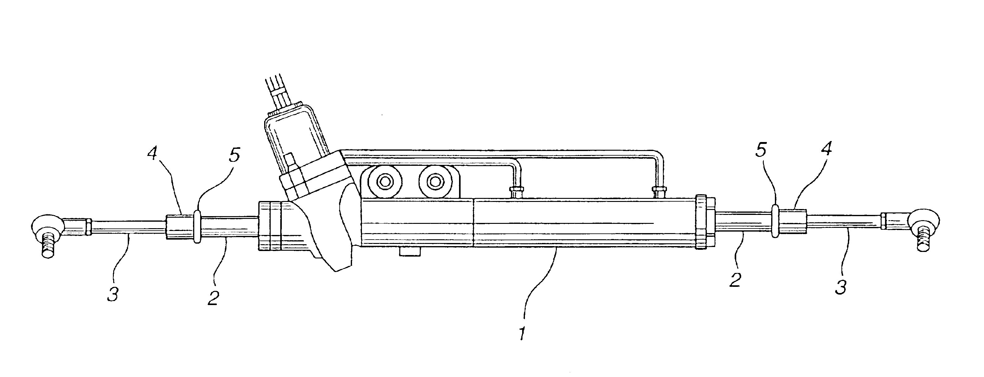
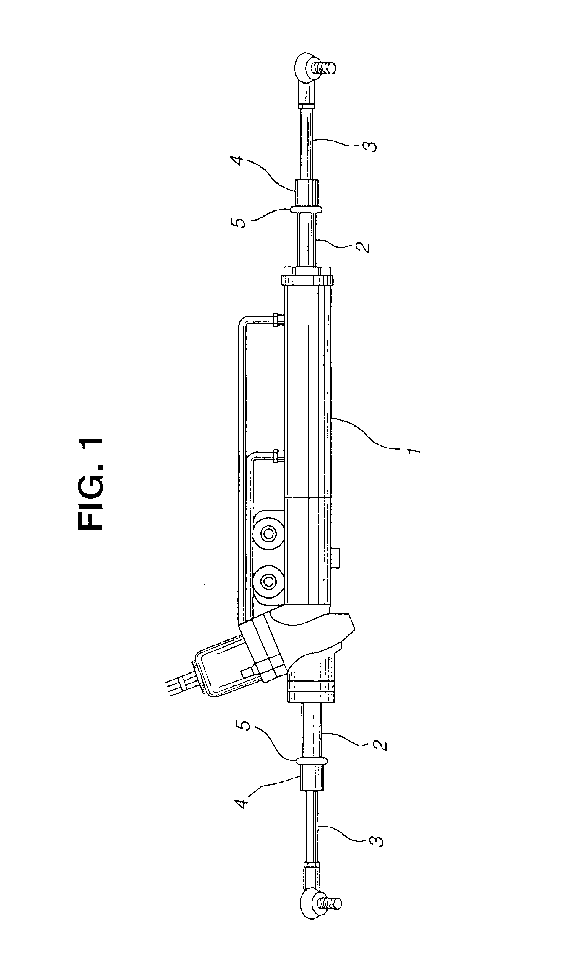
Referring now to FIGS. 1 to 9, more specifically to FIG. 1, a power cylinder (cylinder device) of a power steering system is illustrated. The power cylinder comprises a cylinder (housing) 1 inside which a rack bar or slidable shaft 2 is axially slidably movably disposed. Rack bar 2 has opposite end sections which are extendable out of cylinder 1 and connected respectively to tie rods 3, 3 through sockets (joint members) 4, 4 and stopper members 5, 5. Each tie rod 3 is to be connected to a road wheel (not shown).

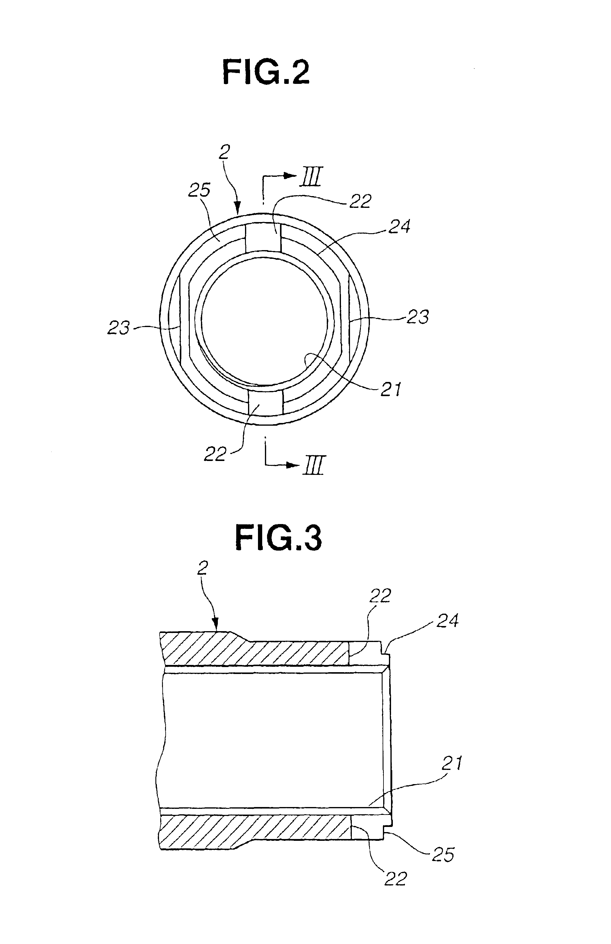
Each of the opposite end sections of rack bar 2 is formed cylindrical and formed at its inner peripheral surface with an internal thread 21 as shown in FIGS. 2 and 3. A tip end portion of each end section of rack bar 2 is formed with two cutouts (axial engagement sections) 22, 22 which are located diametrically opposite to each other. Two cutouts 22, 22 extend along a first diametrically extending plane (not shown) in the end section of the rack bar 2, so that each cutout 22 ...


PUM


Abstract

A cylinder device such as a power cylinder of a power steering system includes a slidable shaft slidably disposed inside a housing. A joint member is connected to the end section of the slidable shaft. A stopper member is disposed between the slidable shaft and the joint member. Here, the end section of the slidable shaft is cutout to form an axial engagement surface. The slidable shaft and the joint member are connected in a condition where the end face of the slidable shaft is in contact with the end face of the joint member so as to from a groove between the axial engagement surface and the joint member. The stopper member is formed annular and has an engagement section formed along its inner periphery. The engagement section is fitted in the groove so that the stopper member is prevented from at least an axial movement.

Description

BACKGROUND OF THE INVENTIONThis invention relates to improvements in a cylinder device of the type including a stopper section for stopping a relative sliding movement between a housing and a shaft (rack bar) extending through and slidably movable in the housing at a position where the sliding movement terminates, for example, a power cylinder of a power steering system, and more particularly to the improvements in technique of the stopper section.Hitherto a variety of such cylinder devices have been proposed and put into practical use. One of them is disclosed in Japanese Utility Model Publication No. 62-3368 relating to a rack-and-pinion steering gear. In this rack-and-pinion steering gear, a socket for a tie rod is connected to an end section of a rack bar (slidable shaft) under being screwed in, in which a stopper member is incorporated to buffer contact between the socket and the end section of a housing. The stopper member is constituted of a metal ring having an opening to be...

Claims


Application Information

Patent Timeline
Patent Type & Authority Patents(United States)
IPC IPC(8): B62D5/22B62D3/00B62D3/12B62D5/20F15B15/24F15B15/00
CPCB62D3/12F15B15/24B62D5/22
Inventor INOUE, KOICHI
Owner HITACHI ASTEMO LTD
Why Eureka
Try Eureka