

Training Apparatus
a training apparatus and glutesexercising technology, applied in the field of training apparatus, can solve the problems of reducing the efficiency of training, unable to achieve effective training, and drawbacks of conventional training machines, so as to reduce the efficiency of training and effectively develop the gluteus maximus muscle
- Summary
- Abstract
- Description
- Claims
- Application Information
AI Technical Summary
Benefits of technology
Problems solved by technology
Method used
Image

Examples
Embodiment Construction
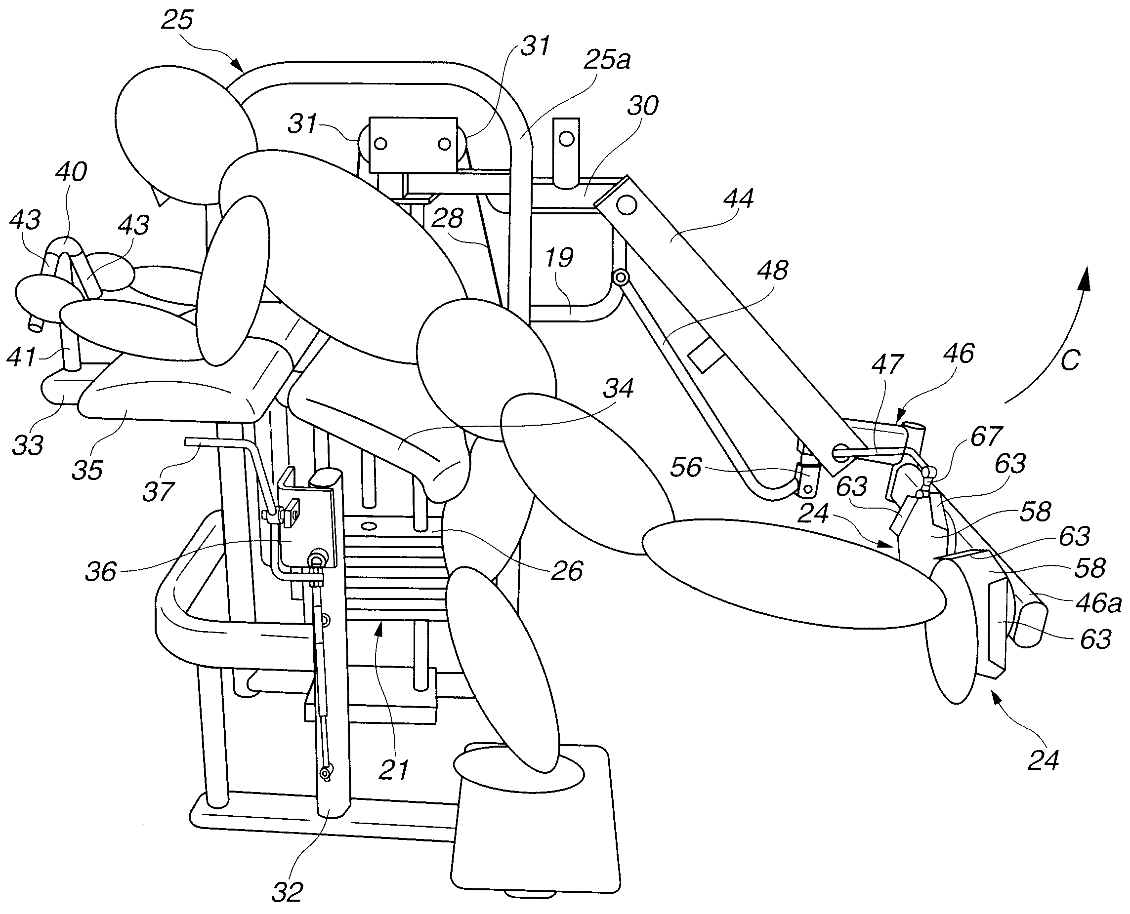
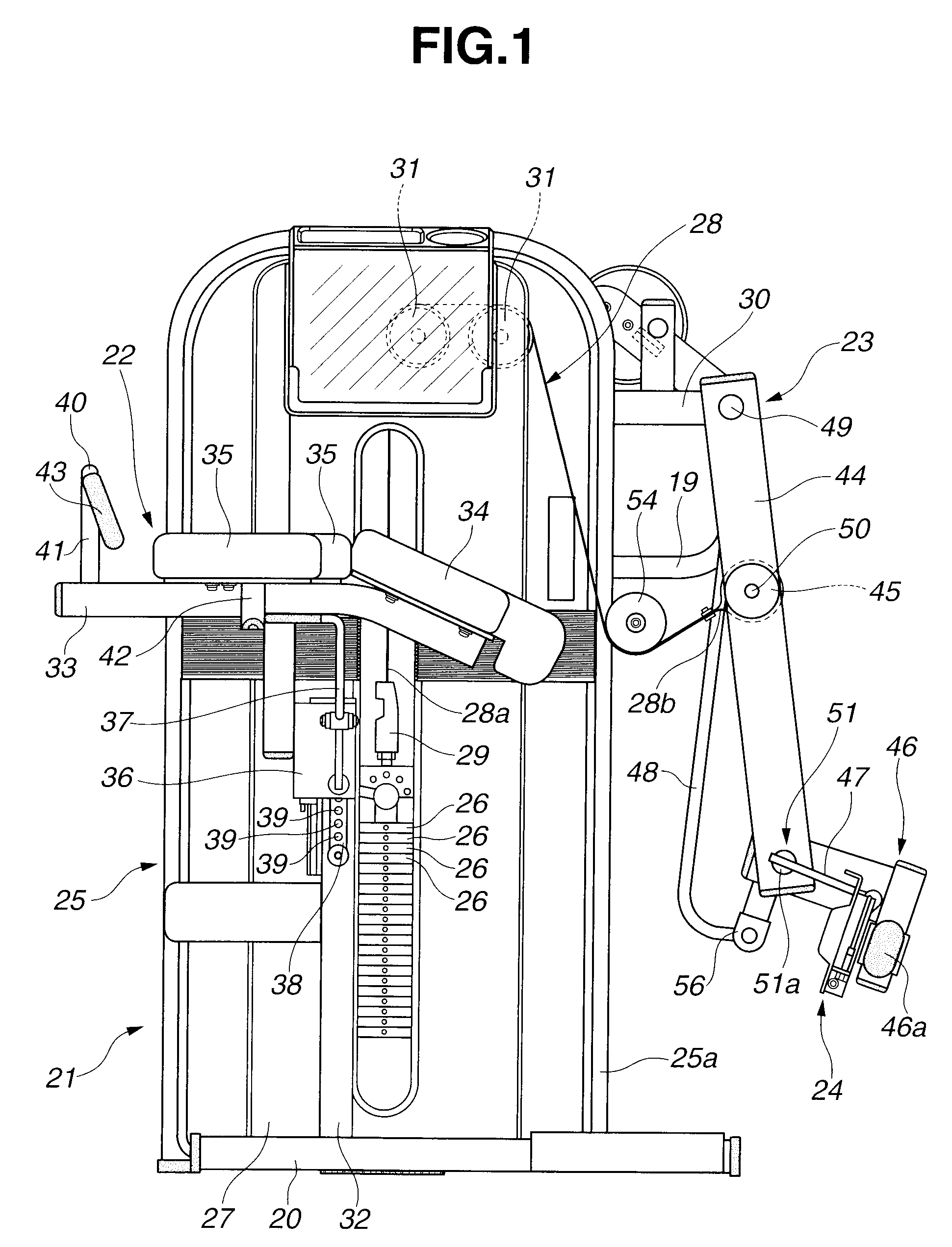
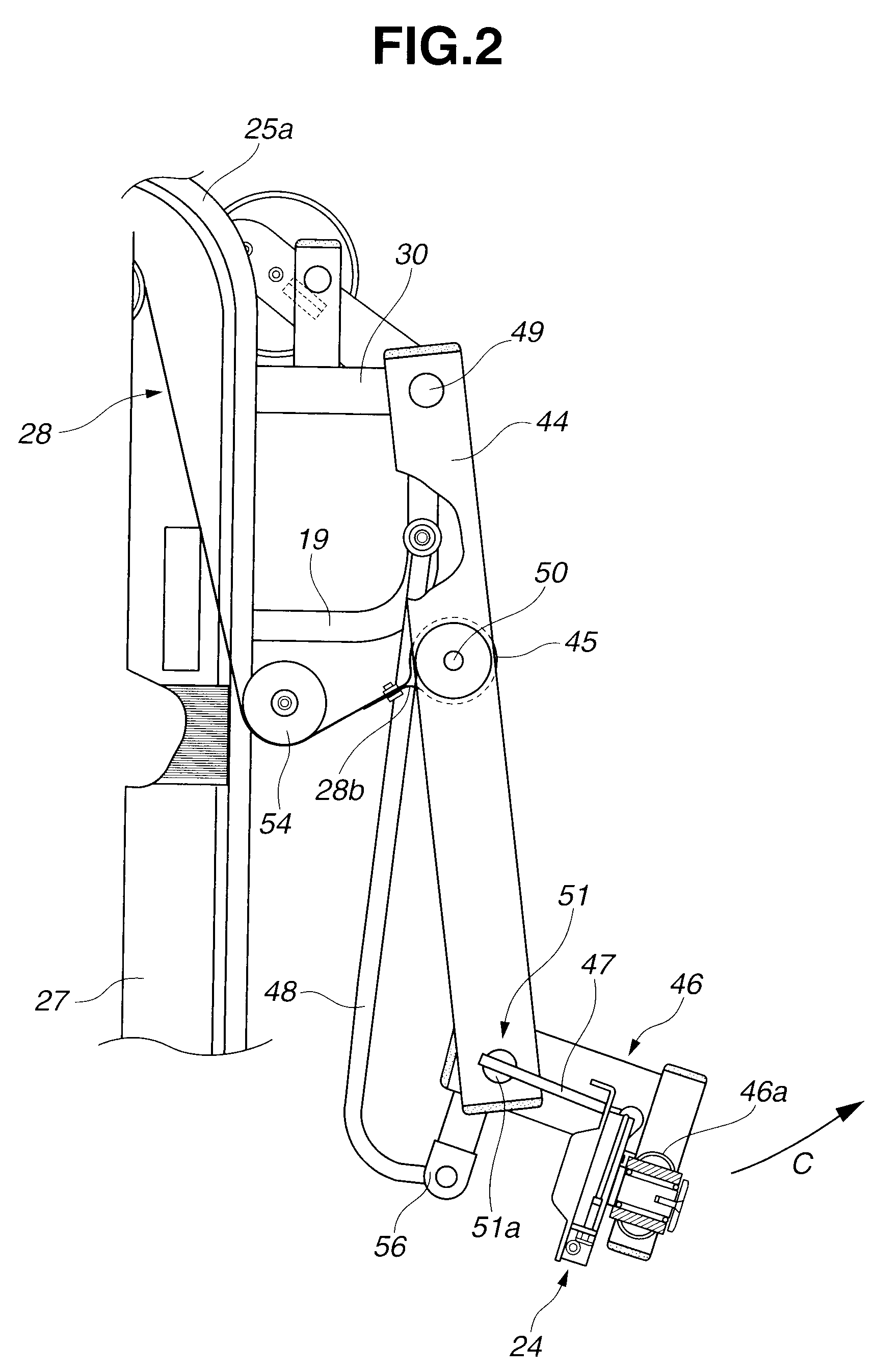
[0024]Referring now to FIGS. 1 to 8, an embodiment of a training apparatus according to the present invention is illustrated. As shown in FIG. 1, the training apparatus according to the present invention comprises a base frame 20 (having opposite frames as shown in FIG. 7 or 8). A load application device 21 is provided mounted on one of the opposite frames of the base frame 20, while a seat section 22 is provided supported on the other of the opposite frames of the base frame 20 so as to face the load application device 21. An arm section 23 to which a load derived from the load application device 21 is transmitted is pivotally provided. A pair of steps 24 is provided to be driven in the directions opposite to each other in linkage with rotation of the arm section 23.
[0025](i) Load Application Device 21
[0026]The load application device 21 includes a rectangularly formed weight frame 25 having an upright side frame 25a, as shown in FIG. 1. A plurality of weight blocks 26 are provided...
PUM
 Abstract
Description
Claims
Application Information