Cooling structure of cylinder head and method for manufacturing cylinder head

a technology of cooling structure and cylinder head, which is applied in the direction of cylinders, combustion engines, machines/engines, etc., can solve the problems of slowing down the flow rate of cooling water, stagnation or residual foreign materials, and difficulty in effectively cooling the area of the cylinder head

Inactive Publication Date: 2002-09-12
TOYOTA JIDOSHA KK
View PDF0 Cites 51 Cited by
  • Summary
  • Abstract
  • Description
  • Claims
  • Application Information

AI Technical Summary

Problems solved by technology

However, to extend the inner space of the water jacket partially may lead to a complicated structure of the inner shape of the water jacket and such complicated shape of the water jacket may slow down the flow rate of the cooling water.
This will cause a stagnation or residual foreign materials left in the water jacket and it may be difficult to effectively cool the area of the cylinder head close to the combustion chamber.
Further, the area of the cylinder head close to the combustion chamber may receive a large force based on the combustion pressure generated during the fuel combustion.
Accordingly, when the water jacket has a complicated shape at the inner space, the stress is concentrated upon the area of the cylinder head by the

Method used


Image

  • Cooling structure of cylinder head and method for manufacturing cylinder head
  • Cooling structure of cylinder head and method for manufacturing cylinder head
  • Cooling structure of cylinder head and method for manufacturing cylinder head

Examples


Embodiment Construction

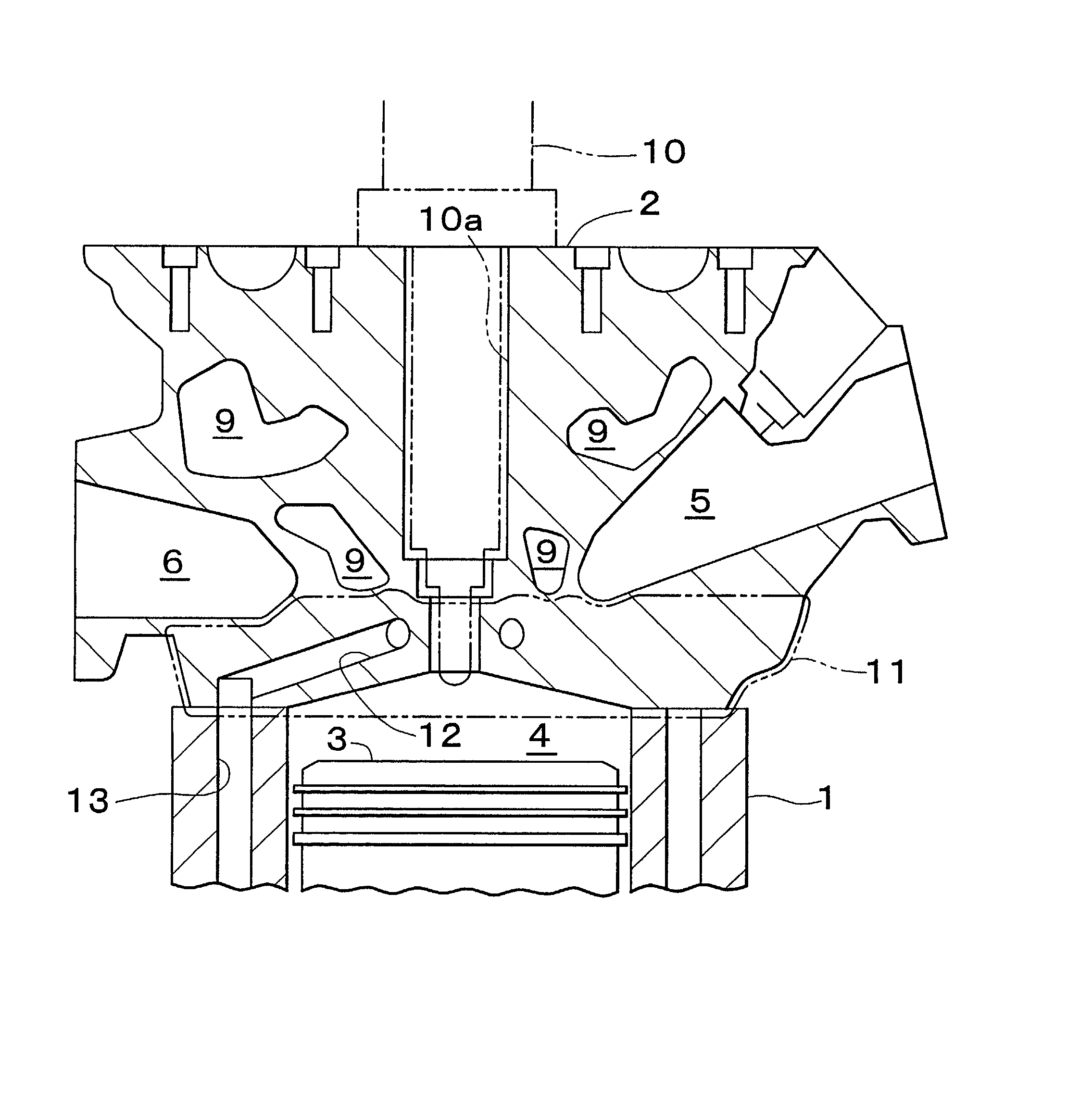
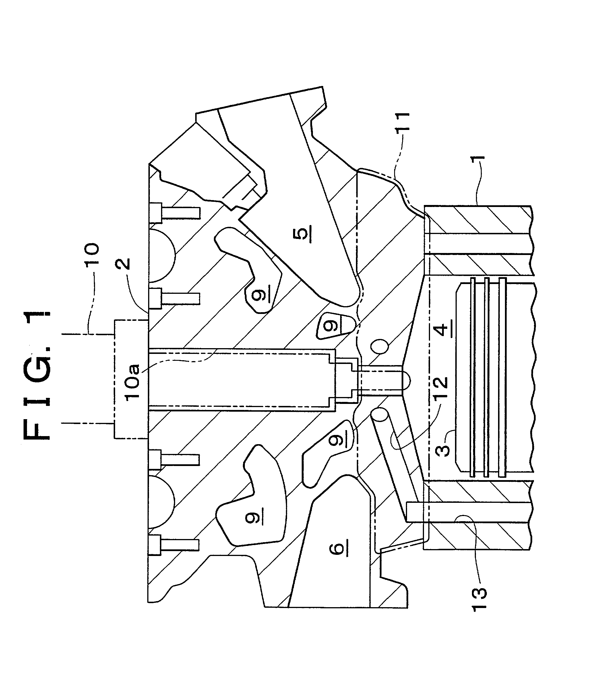
[0027] Referring now to an embodiment of the present invention applied to a cylinder head made of casting aluminum for water cooled type multiple-cylinder diesel engine, with reference to the attached drawings of FIG. 1 through FIG. 3, FIG. 1 shows an enlarged cross sectional view showing the vicinity of a combustion chamber of one cylinder of the engine. This engine includes a cylinder head 2 assembled on upper side of a cylinder block 1 and a piston 3 reciprocal within the cylinder block 1. A combustion chamber 4 is defined by the cylinder head 2 and the piston 3 and is to be supplied with a fuel from a fuel injection nozzle 10. The fuel supplied into the combustion chamber 4 is combusted to reciprocate the piston 3 by the combustion energy generated upon combustion of the fuel to eventually drive the engine.

[0028] In the combustion chamber 4, a intake passage 5 and an exhaust passage 6 are connected under the branched condition (In FIG. 1, only one side of each branched intake an...


PUM


Abstract

In a cylinder head, a cooling water passage with a circular shape (an elliptical shape) in cross section in radial direction is formed at an area (lower layer deck) closer to a combustion chamber than a water jacket in which a cooling water flows. The cooling water passage of the cylinder head is formed by casting by providing a hollow core in a mold and removing the hollow core.

Description

INCORPORATION BY REFERENCE[0001] The disclosure of Japanese patent Application Nos. 2000-062244 filed on Mar. 6, 2001 and 2001-064887 filed on Mar. 8, 2001 including the specification, drawings and abstract are incorporated herein by reference in their entirety.[0002] 1. Field of the Invention[0003] The present invention relates to a cooling structure in an engine and a method for manufacturing a cylinder head.[0004] 2. Description of the Related Art[0005] Generally, in a water-cooled engine, a water jacket is provided inside of a cylinder head and cylinder block to cool the cooling water flowing therethrough. For example, a Japanese patent Laid-open Publication No. 9-242602 discloses a cylinder head in which a shape of the water passage of the water jacket is devised to control a water flow so that a cooling water may flow through an area where the ambient temperature becomes high such as area between the engine valves.[0006] In the engine, combustion chamber defined by the cylinde...

Claims


Application Information

Patent Timeline
IPC IPC(8): F02B3/06F02F1/24F02F1/38F02F1/40F02F1/42
CPCF02B3/06F02F1/242F02F1/38F02F1/40F02F1/4214F02F2001/247
Inventor ISHIGURO, FUMIHISAIKUTA, HIROYUKIAMANO, NORIHIRO
Owner TOYOTA JIDOSHA KK
Why Eureka
Try Eureka