High efficiency multicycle internal combustion engine with waste heat recovery

a multi-cycle, internal combustion engine technology, applied in the direction of machines/engines, combination engines, combination engines, etc., can solve the problems of inefficiency of the system for recovering waste exhaust heat and waste heat from the combustion chamber coolant in a dual-cycle engine, and achieve the effects of improving operating efficiency, reducing specific fuel consumption, and high efficiency

Active Publication Date: 2011-11-22
THERMAL POWER RECOVERY
View PDF69 Cites 51 Cited by
  • Summary
  • Abstract
  • Description
  • Claims
  • Application Information

AI Technical Summary

Benefits of technology

[0018]Depending upon the application of the engine, the cylinder cap which is placed adjacent to a steam exhaust port can be unheated, but if advantageous, is capable of being heated to the temperature of the superheated steam supply or, if desired, is able to provide an intermediate controlled degree of heating to minimize potential power losses. Heating of the cylinder cap makes it possible in some engine applications to achieve high efficiencies which surpass those in what is known as a uniflow steam engine so as to provide additional power from waste combustion heat; an efficiency level that is much higher than in an ordinary counterflow steam engine. The engine also has the flexibility needed under non-uniform steam generator pressure and engine load conditions that occur in vehicles through a provision for variable steam displacement. Another aspect of the invention concerns a more efficient way to recover combustion heat that is contained in the combustion chamber coolant and in the I.C. exhaust gas using an exhaust powered superheater comprising an engine exhaust manifold for supplemental combustion of unburned fuel while also providing for the direct conduction of the heat produced in the combustion chamber to increase the enthalpy of expanding steam within the steam expansion chamber inside of each piston. Engine coolant can be evaporated in the engine-cooling jacket to form steam which is then superheated by I.C. exhaust gases within an engine exhaust manifold for powering the steam expansion chamber within each piston. The invention thus provides an improved heat recovery, heat exchange, steam generator and superheater system for generating steam with a way to better construct a steam expansion chamber, steam cylinder head, valving and heated steam exhaust area. There is also a provision for steam recompression to admission pressure inside of a combustion piston so as to achieve an effective zero clearance volume and a gain in mean Rankine cycle temperature along with a steam supply arrangement that is able to act on each piston within an I.C. engine so as to more effectively economize on fuel, make a more efficient combined gas and steam engine, balance the steam displacement with steam generator output to use steam more efficiently, and provide other features that will be apparent from the following description without the use of a piston rod, crosshead or crosshead guide thereby reducing the reciprocating mass.

Problems solved by technology

Previous systems for recovering waste exhaust heat and waste heat from the combustion chamber coolant in a dual cycle engine have been inefficient.

Method used


Image

  • High efficiency multicycle internal combustion engine with waste heat recovery
  • High efficiency multicycle internal combustion engine with waste heat recovery
  • High efficiency multicycle internal combustion engine with waste heat recovery

Examples


Embodiment Construction

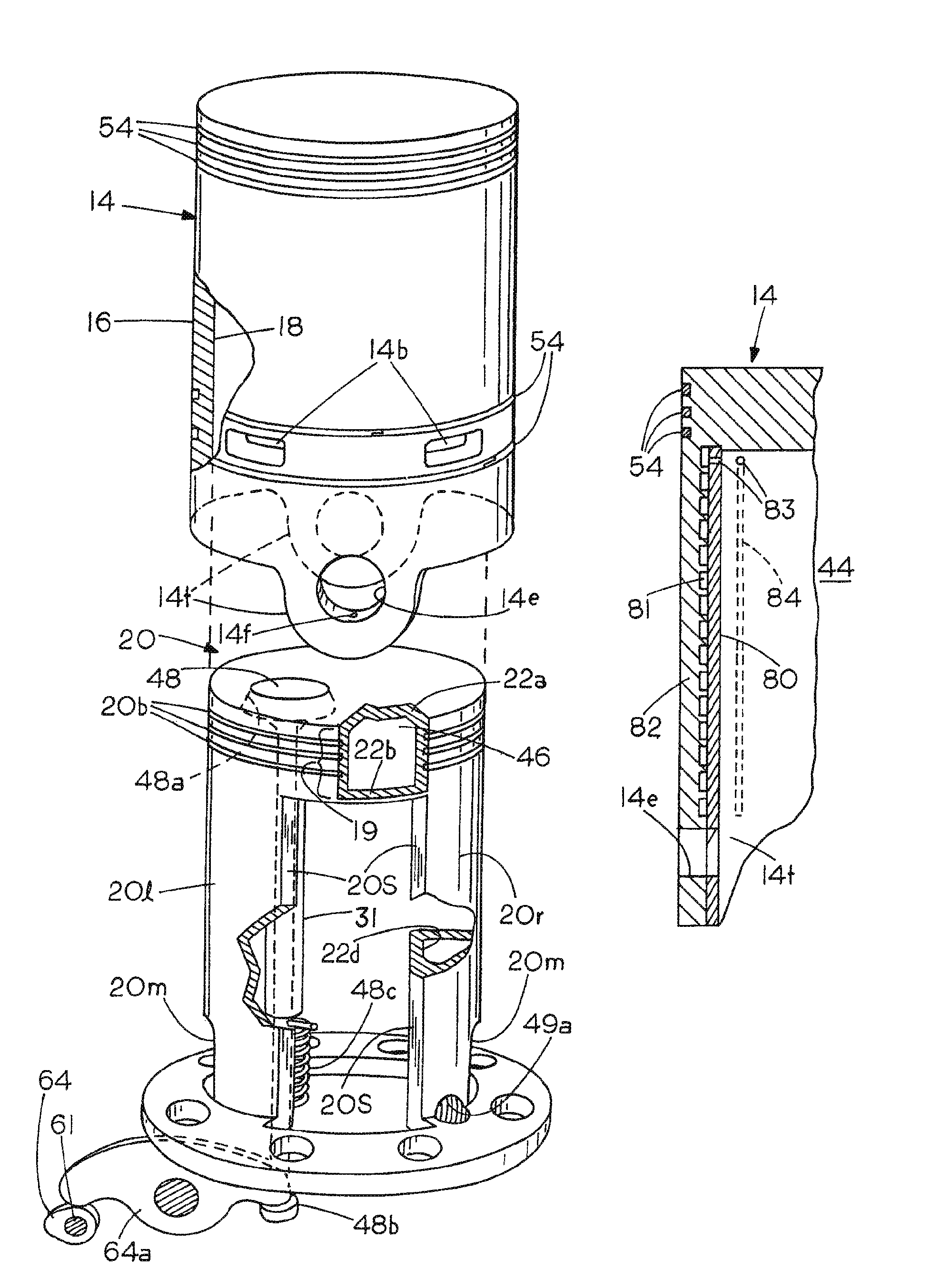
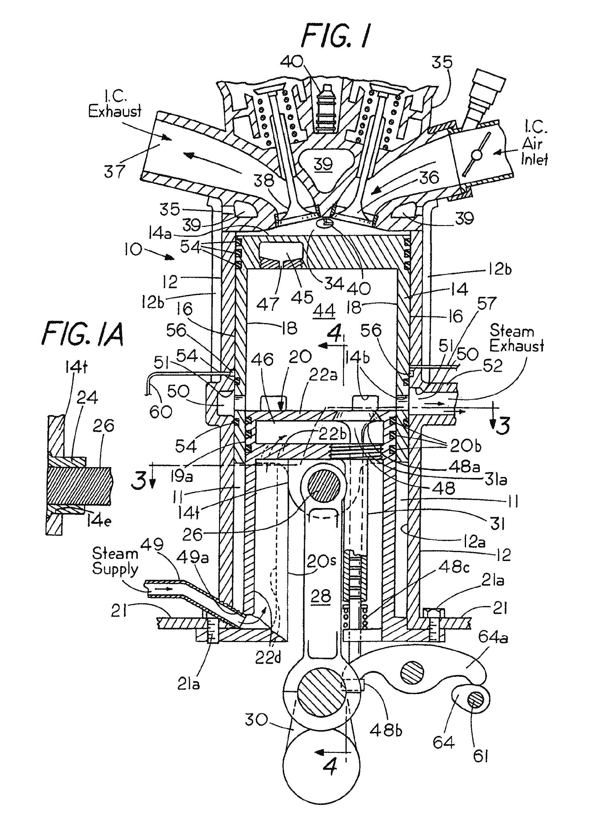
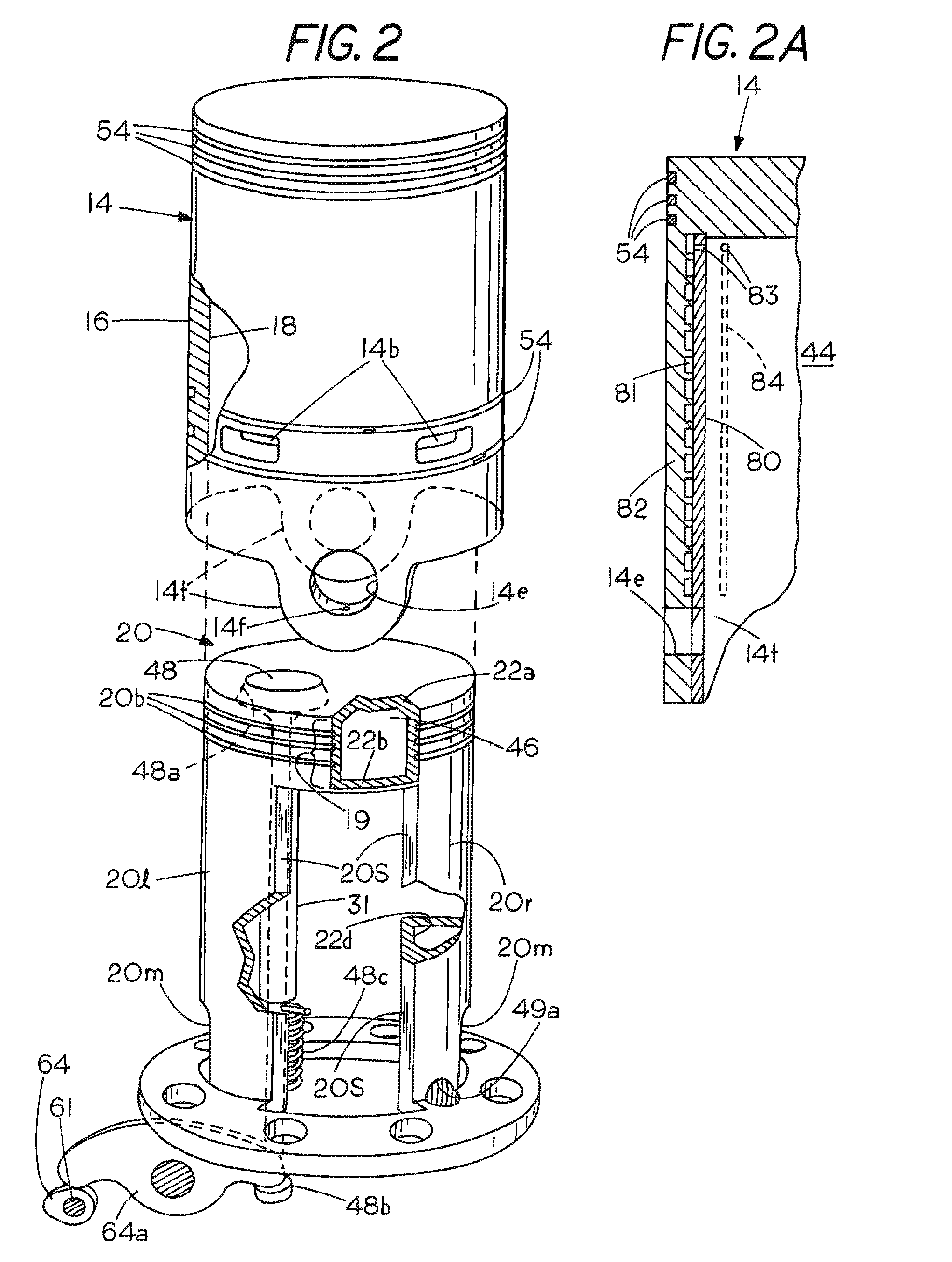
[0019]Refer now to the drawings in which the same numbers refer to corresponding parts in several views. Shown diagrammatically in FIGS. 1-7 is a combination internal combustion engine and steam engine 10 that has a cylinder 12 containing a cup shaped trunk style piston 14 which, unlike ordinary pistons, is machined and ground to precise tolerances both outside at 16 as well as in the inside at 18 and is positioned to reciprocate within an annular space 11 between the inside wall 12a of the cylinder 12 and a stationary steam cylinder head. The piston 14 is provided with two compression rings and at the bottom an oil ring all marked 54. Near the lower end of the piston are circumferentially arranged exhaust openings 14b in the piston skirt. Positioned above and below the exhaust openings 14b are additional compression rings 54 (FIGS. 1 and 2). While a single cylinder and piston is shown for convenience in some views, the invention is of course applicable to multi-cylinder engines as ...


PUM


Abstract

A high efficiency combined cycle internal combustion and steam engine includes a cylinder and a piston with an internal combustion chamber outward of the piston, a fixed cylinder cap and a steam expansion chamber inside the piston. The cylinder cap can be heated to reduce condensation of steam entering from a steam generator fired by waste combustion heat. Following exhaust, residual steam can be recompressed prior to admitting the next charge of steam. A wrist pin connected to an inner end of the piston skirt inwardly of the cylinder cap is coupled to a connecting rod secured to a crankshaft. One valve or a pair of steam inlet valves are connected to communicate in series within the cylinder cap inside the piston. The steam mass admitted is regulated to reduce fuel consumption. Coolant can be superheated in the combustion exhaust manifold.

Description

[0001]This application is a continuation-in-part of Ser. No. 12 / 492,773 filed Jun. 26, 2009. The applicant claims the benefit of the following provisional and non-provisional applications entitled INTERNAL COMBUSTION ENGINE WITH AUXILIARY STEAM POWER RECOVERED FROM WASTE HEAT, Ser. No. 12 / 387,113 filed Apr. 28, 2009; Ser. No. 60 / 905,732 filed Mar. 7, 2007; Ser. No. 12 / 075,042 filed Mar. 7, 2008 (U.S. Pat. Pub. No. 2008 / 0216480A1); Ser. No. 61 / 192,254 filed Sep. 17, 2008, Ser. No. 61 / 194,608 filed Sep. 29, 2008 and Ser. No. 12 / 492,773 filed Jun. 26, 2009 which are incorporated herein by reference.FIELD OF THE INVENTION[0002]This invention relates to internal combustion engines with supplemental steam power obtained from waste combustion heat and to a combination internal combustion (I.C.) engine and steam engine.BACKGROUND[0003]Internal combustion piston engines although highly developed, dependable and relied upon for almost all road transportation throughout the world generally los...

Claims


Application Information

Patent Timeline
Patent Type & Authority Patents(United States)
IPC IPC(8): F01K23/06F01K27/00F01K23/10F02G3/00F02B75/30F01K13/00F02B33/44F02B75/28
CPCF01B7/20F01B17/04F01B21/02F02B41/00F02B75/30Y02T10/14Y02T10/16Y02T10/166Y02T10/12
Inventor HARMON, SR., JAMES V.
Owner THERMAL POWER RECOVERY
Why Eureka
Try Eureka