
Ethanol recovery process and apparatus for biological conversion of syngas components to liquid products

Active Publication Date: 2009-08-27
SYNATA BIO INC
View PDF25 Cites 76 Cited by
  • Summary
  • Abstract
  • Description
  • Claims
  • Application Information

AI Technical Summary

Benefits of technology

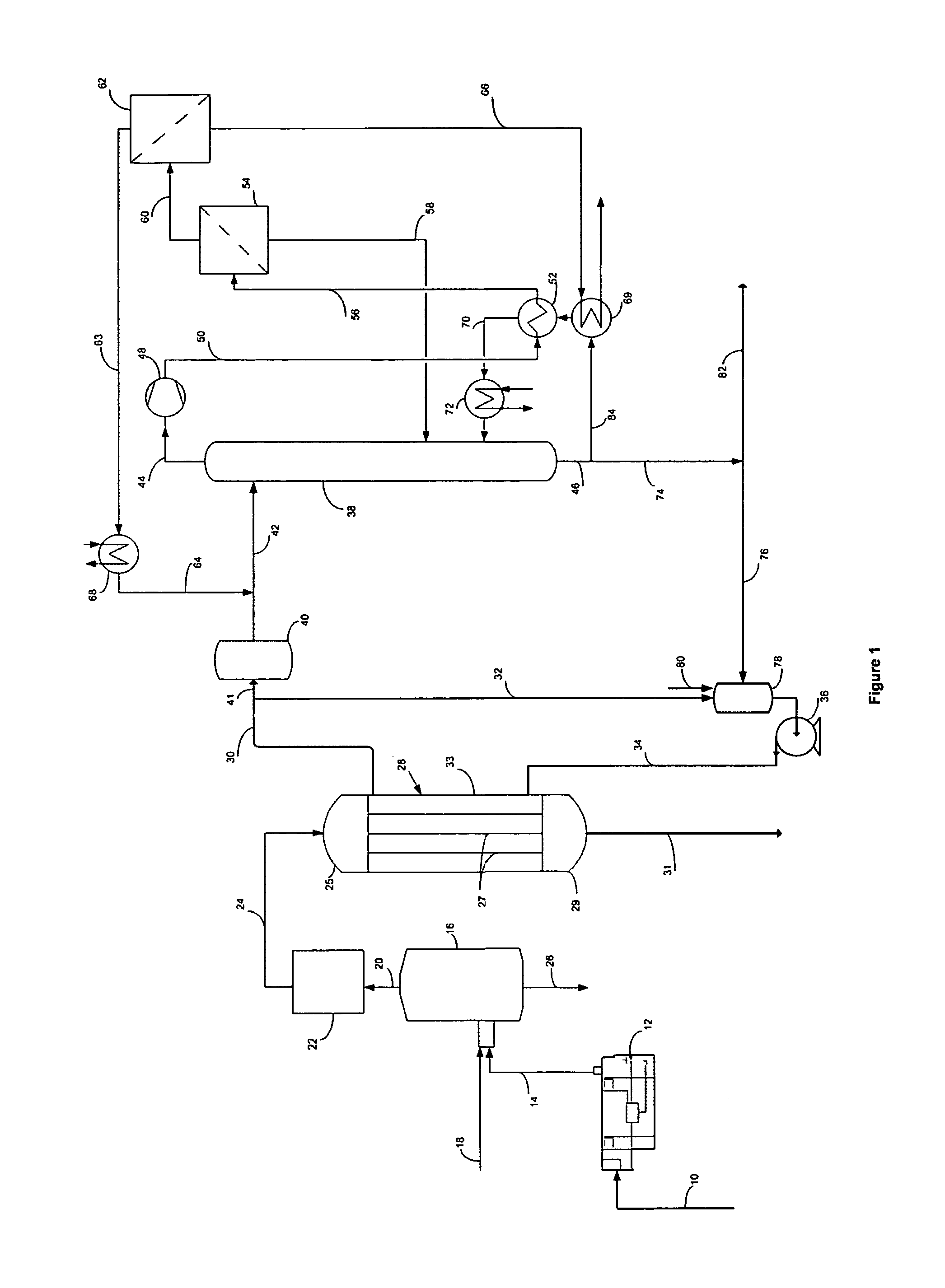
[0014]It has been found the coupling of a bioreactor with a separation zone that uses vacuum distillation followed by vapor phase permeation can efficiently and economically separate ethanol when present at low concentration in an aqueous fermentation broth. Having a system of practical ethanol recovery in such low concentrations is essential to utilizing syngas generated from biomass. Biomass provides an extensive and renewable source for the generation of syngas and the ultimate production of ethanol.
[0017]The integration of the vacuum distillation column with the low ethanol concentration effluent brings numerous advantages to the operation and efficiency of the process arrangement. The distillation column enables efficient ethanol recovery with a fermentation broth having ethanol concentrations as low as 1%. There is an important need for a way to efficiently recover ethanol from such fermentation broths given the low ethanol tolerance of the anaerobic bacteria that are suitable for biomass derived feed gas. This separation arrangement succeeds in taking the fermentation broth with ethanol as low as 1 to 4% and generating an ethanol overhead from the distillation column of over 30% and as high as 50%. The stripping function of the distillation column together with the large volume of liquid coming from the column bottoms minimizes or eliminates fouling problems of the membranes by protecting them from bacterial cells and other non-volatile impurities of the fermentation broth. Since the distillation is conducted under vacuum, the bottoms do not require high temperatures that result in the formation of toxic by-products. Thus, the majority of the column bottoms can return directly to the bioreactor. This return enables a conservation of water and the uptake of acetic acid and / or butyric acid that the anaerobic bacteria can convert to more ethanol in the bioreactor. A small fraction of the column bottoms undergoes purging of acetates and other insolubles via an anaerobic digestor that converts these materials to methane. Recovered methane gas can provide a further source of process energy. For example the methane can be used as an energy source in the gasification step.
[0018]Further advantages derive from the limited number of phase changes from the low operating temperatures of the vacuum distillation column and the downstream processing of the ethanol overhead in the permeation units. Operation of the vacuum distillation column at moderate temperatures reduces the need for reflux over conventional columns and minimizes the vapor-liquid phase changes. In fact, when the concentration of ethanol in the effluent from the bioreactor exceeds 3 wt %, the process can operate without recycle of any distillation column overhead. Furthermore, the vapor permeation units operate at high efficiency since there are no phase changes. The first permeation unit provides vapor for the distillation column in the form of a water rich permeate. The compression energy associated with the latent heat of vaporization of the dehydrated ethanol product is also recovered via heat exchange with the vacuum column bottoms.
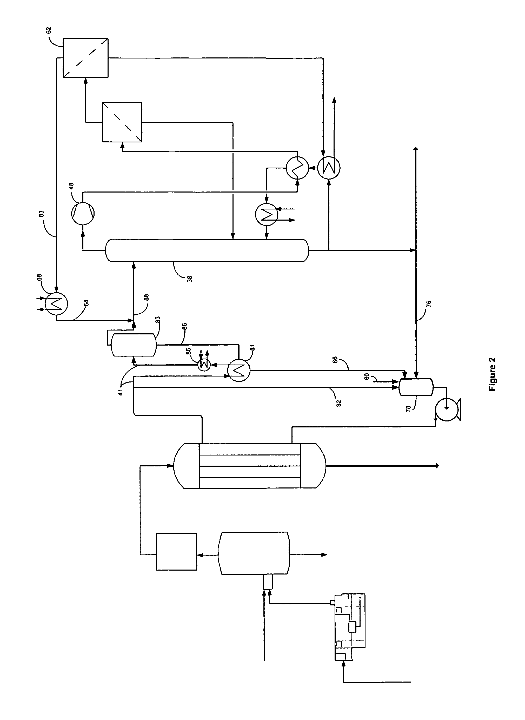
[0019]Another form of this invention may incorporate a flash zone between the bioreactor or bioreactor and the vacuum distillation column. The low concentration of the ethanol stream to which this invention applies makes a flash step particularly useful. Since the alcohol concentration at typical equilibrium conditions is 9 to 12 times greater in the vapor phase than in the liquid phase the flash step can improve separation efficiency. The flash step can provide a highly efficient enrichment of the ethanol containing stream before it enters the vacuum distillation column. The flash zone provides the most benefit at lower concentrations of ethanol in the dilute ethanol stream. Even small reductions in the pressure of the broth can achieve useful flash ratios.
[0020]The particular configuration of the flash zone and its specific integration into the bioreactor and recovery system may take many forms. The flash zone may receive all or only a portion of the fermentation broth that passes to the vacuum stripper for recovery of the ethanol. Most bioreactor arrangements will employ a circulation loop to circulate fermentation broth around the bioreactor and the flash zone may provide part of the broth circulation. The simplicity of the flash zone may also permit its use as part of the purification step to provide dilute ethanol to the vacuum stripper column. To operate, the flash zone basically requires only a heat addition equal to the latent heat of vaporization. This heat may be supplied within the flash zone by a reboiler to avoid excessive heating of the liquid broth. Since the flash zone requires only low temperature heat inputs there are numerous opportunities for beneficial heat inputs and heat exchange.

Problems solved by technology

The availability of agricultural feedstocks that provide readily fermentable carbohydrates is limited because of competition with food and feed production, arable land usage, water availability, and other factors.
However, the very heterogeneous nature of lignocellulosic materials that enables them to provide the mechanical support structure of the plants and trees makes them inherently recalcitrant to bioconversion.
Furthermore, conventional yeasts are unable to ferment the C5 sugars to ethanol and lignin components are completely unfermentable by such organisms.
For all of these reasons, processes based on a pretreatment / hydrolysis / fermentation path for conversion of lignocellulose biomass to ethanol, for example, are inherently difficult and often uneconomical multi-step and multi conversion processes.
And very large quantities of these gases are required.
Furthermore, the anaerobic microorganisms that bring about these bioconversions generate very little metabolic energy from these bioconversions.
These systems are expensive and require extensive maintenance and cleaning of the membranes to maintain the fluxes and other performance parameters.
They suffer from either being very large or unable to provide sufficient gas dissolution rates.
These materials can impose impurities into the separation processes thereby imposing additional challenges to efficient and economical ethanol recovery.
These patents describe the separation of organic mixtures with concentrations as low as 1% but do not provide any solution to the problem of impurities or undissolved materials.

Method used


Image

  • Ethanol recovery process and apparatus for biological conversion of syngas components to liquid products
  • Ethanol recovery process and apparatus for biological conversion of syngas components to liquid products

Examples


example 1

[0057]For convenience this invention is further described in the context of a calculated example using a membrane type bioreactor. Such description is not intended to limit the separation described herein to the particular arrangement of this example or to any particular bioreactor arrangement. Any bioreactor producing ethanol in a liquid medium may be integrated with the separation elements of this invention.

[0058]To establish a conversion level of a typical syngas type feed a Liqui-Cel® membrane contactor MiniModule® 1×5.5 from Membrana (Charlotte, N.C.) is used as a membrane supported bioreactor for the conversion of carbon monoxide and hydrogen into ethanol. This membrane module contains ×50 microporous hydrophobic polypropylene hollow fibers with 40% porosity and 0.04 μm pore size. The fiber outer diameter is 300 μm and internal diameter 220 μm. The active membrane surface area of the module is 0.18 m2. A gas containing 40% CO, 30% H2, and 30% CO2 is fed to the lumen of the fib...

example 2

[0061]The conversion rate and flow rates of Example 1 were scaled up to provide input for a calculated example demonstrating the separation of dilute ethanol stream in the separation section of the process. In accordance with the separation section depicted in FIG. 1, 1136 kg / hr of an ethanol effluent having an ethanol concentration of 1 wt % flows through a purifier while the remaining 22710 kg / hr of an ethanol effluent enters a recirculation loop for its return the bioreactor as a broth fraction.

[0062]The dilute ethanol from the purifier flows into an upper section of the vacuum distillation column at a temperature of 76° C. The vacuum distillation column provides 20 stages of separation. Overhead vapor having an ethanol concentration of 52.5 wt % flows from the vacuum column at a rate of 25.1 kg / hr and a temperature of 73° C. Compression of the vapor to 1.6 atm raises its temperature to 177° C.

[0063]Cooling of the vapor in the vacuum column reboiler loop lowers its temperature to...


PUM


Abstract

Ethanol and other liquid products produced by the contacting CO and / or a mixture of CO2 and H2 with a microorganism in a bioreactor are separated using a combination of distillation and vapor permeation membranes. The bioreactor passes an effluent with an ethanol concentration of 1 to 6 wt % to a distillation column that produces an overhead vapor stream enriched in ethanol. A series of vapor permeation membranes retain ethanol as retentate and produce a 99 wt % or higher ethanol product. Ethanol depleted permeate streams flow back to the column and the bioreactor. Coupling a bioreactor with distillation and pervaporation efficiently and economically separates ethanol when present at low concentration in an aqueous fermentation broth. The separation arrangement may also include a flash zone ahead of the distillation column to raise the concentration of the ethanol in the input stream to the distillation column.

Description

FIELD OF THE INVENTION[0001]This invention relates to the biological conversion of CO and mixtures of CO2 and H2 to liquid products and the recovery of ethanol from the effluent stream of such conversions.DETAILED DESCRIPTIONBackground[0002]Biofuels production for use as liquid motor fuels or for blending with conventional gasoline or diesel motor fuels is increasing worldwide. Such biofuels include, for example, ethanol and n-butanol. One of the major drivers for biofuels is their derivation from renewable resources by fermentation and bioprocess technology. Conventionally, biofuels are made from readily fermentable carbohydrates such as sugars and starches. For example, the two primary agricultural crops that are used for conventional bioethanol production are sugarcane (Brazil and other tropical countries) and corn or maize (U.S. and other temperate countries). These processes ordinarily use the readily fermentable carbohydrates in relatively high concentration so that the result...

Claims


Application Information

Patent Timeline
IPC IPC(8): C12P7/14
CPCC12P7/065Y02E50/343Y02E50/17C12P7/08Y02E50/10Y02E50/30
Inventor DATTA, RATHINBASU, RAHULGRETHLEIN, HANS E.
Owner SYNATA BIO INC
Learn More