Cylinder head cooling structure for an internal combustion engine, including an oil temperature sensor and an oil temperature control system

a cooling structure and internal combustion engine technology, applied in the direction of cylinders, machines/engines, mechanical equipment, etc., can solve the problems of insufficient cooling, high heat load, and insufficient cooling of the cooling fins on the outer peripheral portions of the internal combustion engin

Active Publication Date: 2006-03-30
HONDA MOTOR CO LTD
View PDF7 Cites 51 Cited by
  • Summary
  • Abstract
  • Description
  • Claims
  • Application Information

AI Technical Summary

Benefits of technology

[0043] According to the fifteenth aspect of the invention, a dead space below the chain tensioner is utilized effectively. Further, since the chain tensioner is a more rigid body than the temperature sensor, and since the temperature sensor is provided below the chain tensioner, the temperature sensor is prevented from being contacted by an article by the chain tensioner.

Problems solved by technology

Since, however, the periphery of spark plug mounting holes and the periphery of combustion chamber-side openings of intake ports and exhaust ports are within the internal combustion engine, sufficient cooling cannot be performed by the heat radiation operation of cooling fins on the outer peripheral portions of the internal combustion engine.
Therefore, the periphery of the spark plug mounting holes is cooled by the oil, but the periphery of the intake port and the exhaust port, which have high heat loads, is not sufficiently cooled.
In the conventional configuration, since the thermostat is integrated with the oil filter and is attached to the front of the engine, it is difficult to maintain the oil filter, and the external appearance of the engine is degraded.
In terms of oil used for cooling an internal combustion engine, therefore, the oil temperature control for a portion intended to be cooled tends to slow.
On the other hand, if the temperature sensor is arranged on a front face of the cylinder, and since the detection value of the sensor is varied by an influence of being exposed to water or the like, a protective member is required, and then the cost increases.
Further, since an engine control unit (ECU), which uses the detected internal combustion temperature to control fuel injection and / or ignition, is usually placed rearward of the internal combustion engine, if the temperature sensor is provided downwardly or forwardly of the cylinder, then the wires from the temperature sensor to the ECU become undesirably long.

Method used


Image

  • Cylinder head cooling structure for an internal combustion engine, including an oil temperature sensor and an oil temperature control system
  • Cylinder head cooling structure for an internal combustion engine, including an oil temperature sensor and an oil temperature control system
  • Cylinder head cooling structure for an internal combustion engine, including an oil temperature sensor and an oil temperature control system

Examples


Embodiment Construction

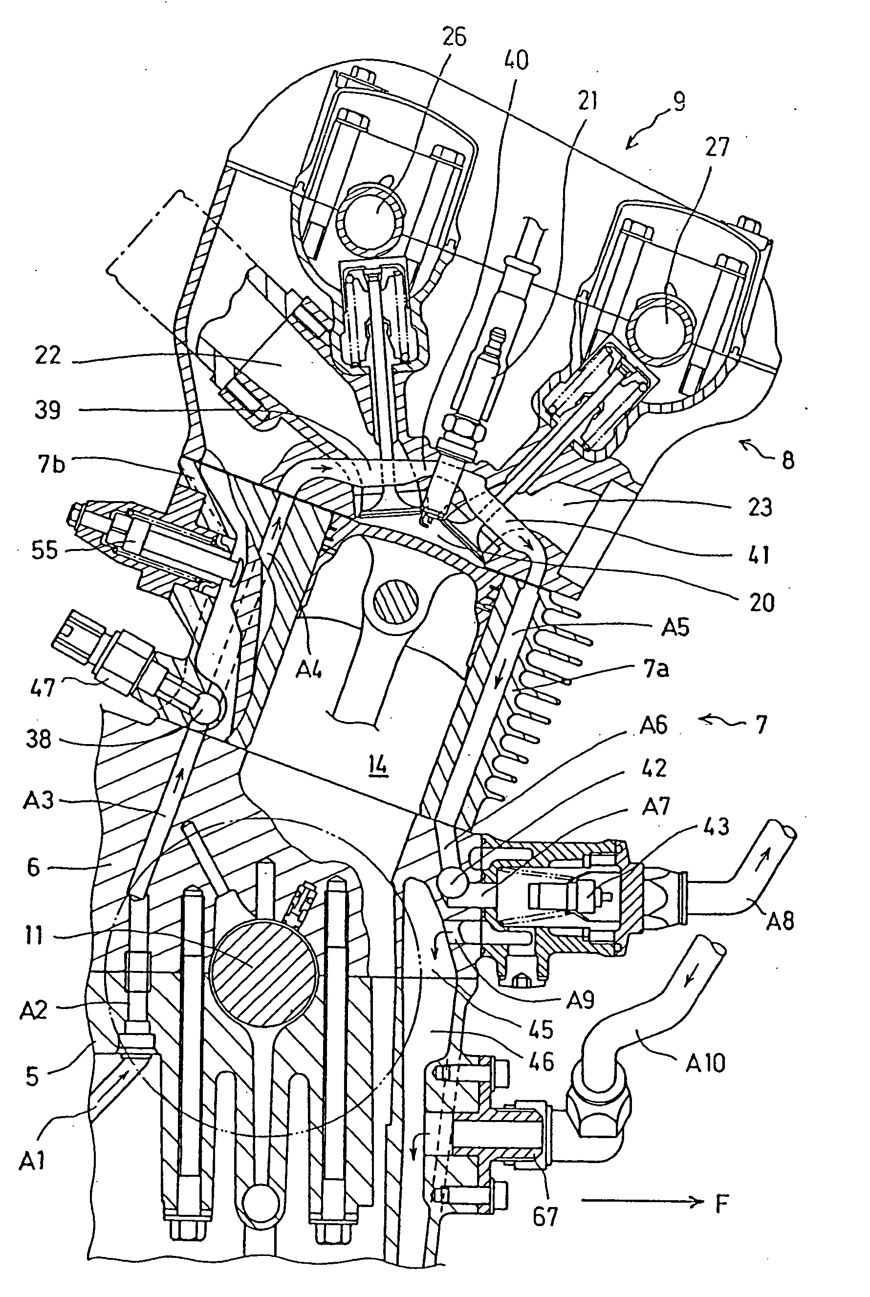
[0055] A selected illustrative embodiment of the invention will now be described in some detail, with reference to the drawings. It should be understood that only structures considered necessary for clarifying the present invention are described herein. Other conventional structures, and those of ancillary and auxiliary components of the system, are assumed to be known and understood by those skilled in the art.

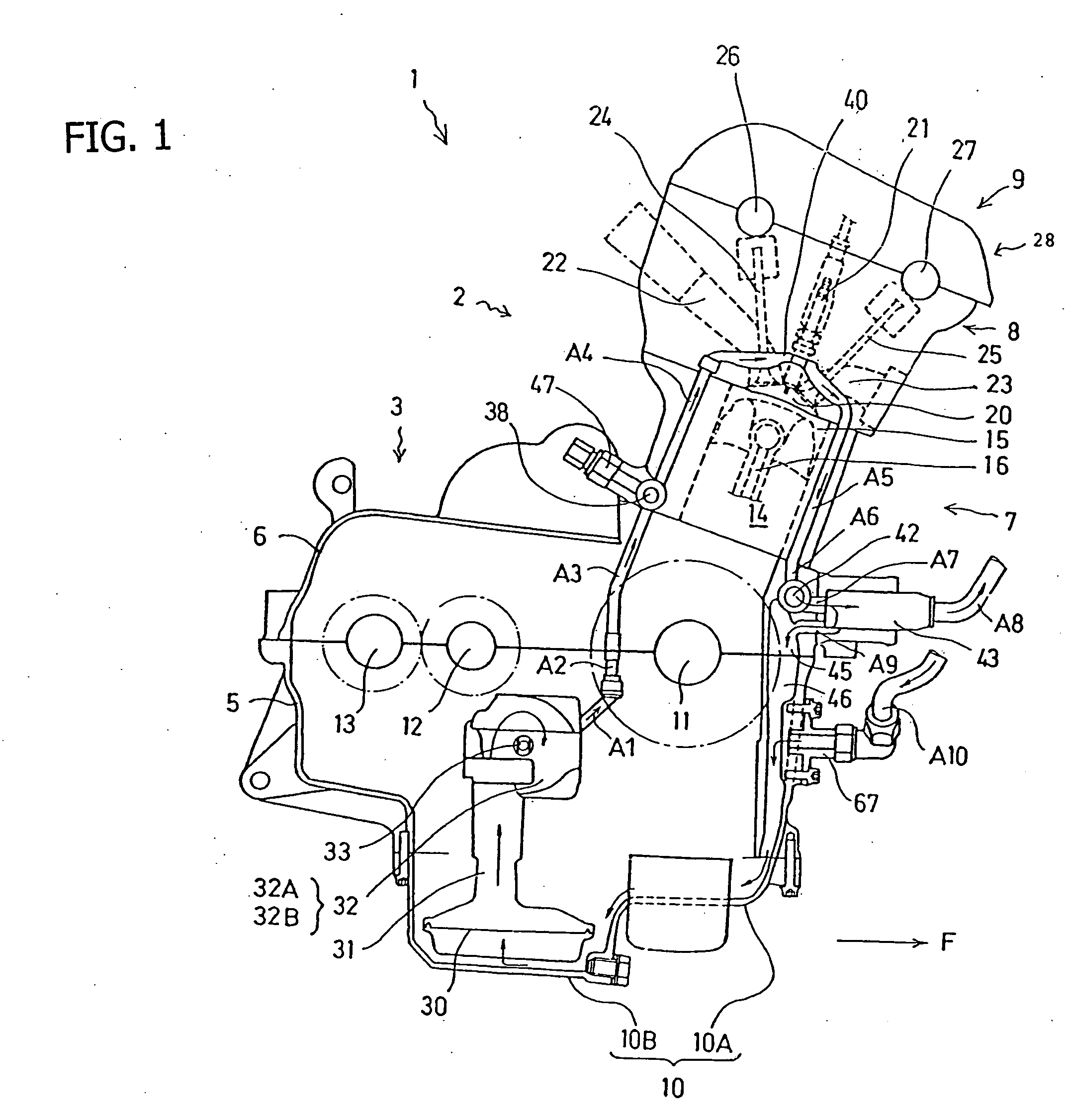
[0056]FIG. 1 is a view showing a cooling system oil circuit on a view of a vertical section of a four-cylinder DOHC wet sump type internal combustion engine 1 according to an embodiment of the present invention as viewed from the right side. An arrow mark F indicates the forward direction of the internal combustion engine 1. The internal combustion engine 1 includes a power generation section 2 and a transmission section 3 integrated with each other. An outer shell of the internal combustion engine 1 is formed from a lower crankcase 5, an upper crankcase 6, a cylinder block ...


PUM


Abstract

A cylinder head cooling structure and an oil temperature control system are provided for an internal combustion engine having a plurality of cylinders, each having a plurality of intake ports and a plurality of exhaust ports. The engine includes cooling oil jackets surrounding the spark plugs in the cylinder head, a thermostat attached to the front surface of the crankcase independently of an oil filter, and an oil temperature sensor disposed on a rear face of the cylinder block above the crankcase in an oil supply path formed on the cylinder rear face for supplying oil to the oil jackets. Oil passages conducting oil into the oil jacket are provided between two separate parts of a bifucated intake port and between two separate parts of a bifurcated exhaust port, and only cooling system oil reaching high temperatures is allowed to flow through the thermostat, thereby improving temperature control response.

Description

CROSS-REFERENCE TO RELATED APPLICATIONS [0001] The present invention claims priority under 35 USC 119 based on Japanese patent applications No. 2004-286405, No. 2004-286406, and No. 2004-286408, each filed on Sep. 30, 2004. The subject matter of these priority documents is incorporated by reference herein. BACKGROUND OF THE INVENTION [0002] 1. Field of the Invention [0003] The present invention relates to cylinder head cooling structure for a four-cycle air-cooled internal combustion engine for a vehicle such as a motorcycle. The cylinder head cooling structure includes an oil temperature control system for cooling oil that, if necessary, circulates to cool a high temperature portion in an internal combustion engine by circulating the oil to an oil cooler according to the temperature of the oil. The cooling structure further includes an arrangement for an oil temperature sensor that makes it possible to precisely detect a cooling system oil temperature as a representative value of t...

Claims


Application Information

Patent Timeline
Patent Type & Authority Applications(United States)
IPC IPC(8): F02F1/36F02F1/42F01P3/00
CPCF01M5/007F01M11/02F01P3/02F01P7/16F01P2025/40F01P2003/006F01P2003/022F01P2003/024F01P9/00
Inventor GOKAN, YOSHITSUGUYAMAMOTO, KATSUJI
Owner HONDA MOTOR CO LTD
Why Eureka
Try Eureka