
Calendar interface

a calendar and interface technology, applied in the field of calendar interfaces, can solve the problems of complex calendars, users having difficulty in easily assessing the information being presented, and further exacerbated problems

Active Publication Date: 2017-05-04
MRP SYST
View PDF11 Cites 15 Cited by
  • Summary
  • Abstract
  • Description
  • Claims
  • Application Information

AI Technical Summary

Benefits of technology

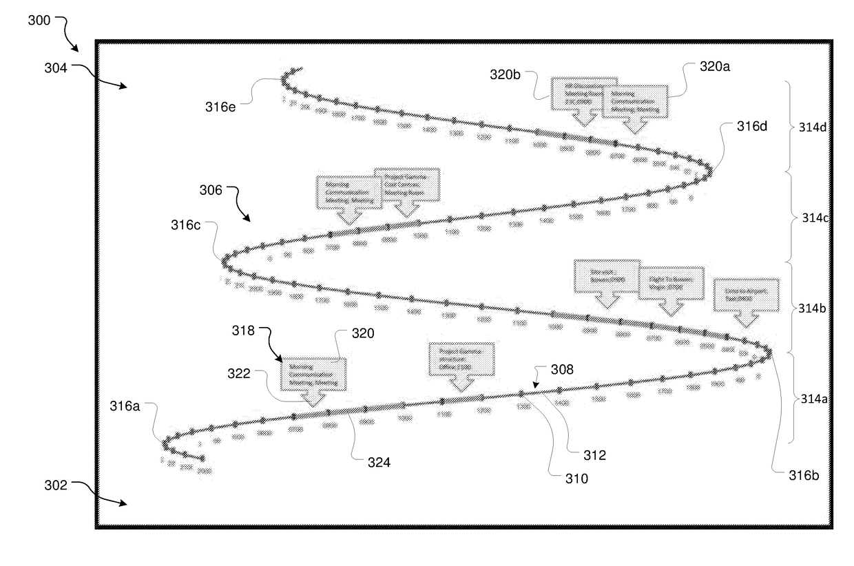
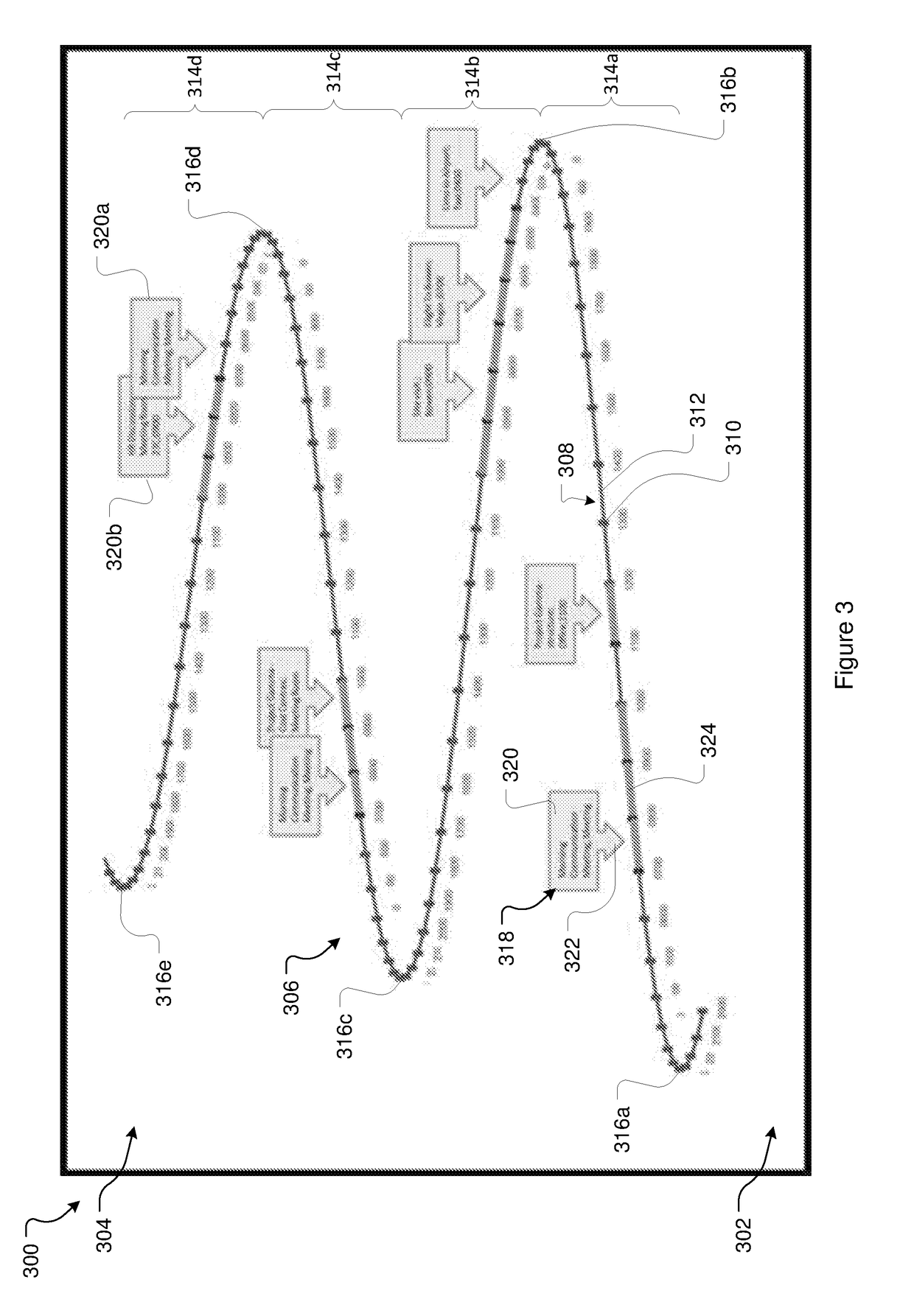
The patent describes a computer method and system for displaying a calendar interface on an electronic device. The method involves determining the total time period, segment duration, and interval duration to create timeline coordinates. A timeline is then displayed based on these coordinates, with each calendar item placed on the timeline at a position related to its associated time. The timeline is designed to have multiple segments, with each segment representing a period of time within the total time period. The method may also include displaying multiple timelines, adjustable reference lines, and applying a theme to the calendar interface. The technical effect of this patent is to provide a more efficient and intuitive way for users to view and interact with a calendar on their device.

Problems solved by technology

A problem with this, however, is that as more information is included and displayed calendars become visually complex.
This can lead to users having difficulty in easily assessing the information being presented.
This can be particularly problematic when viewing calendars on portable electronic devices with smaller screens, and is further exacerbated if a user attempts to view multiple calendars at the same time.

Method used


Image

  • Calendar interface
  • Calendar interface
  • Calendar interface

Examples


Embodiment Construction

[0036]The present invention generally relates to systems and methods for generating and displaying a calendar interface on an electronic device. As is described in detail below, the interface allows for the generation, viewing, and manipulation of calendar data.

Computer Processing System

[0037]The present invention is necessarily implemented using an electronic device. The electronic device is, or will include, a computer processing system.

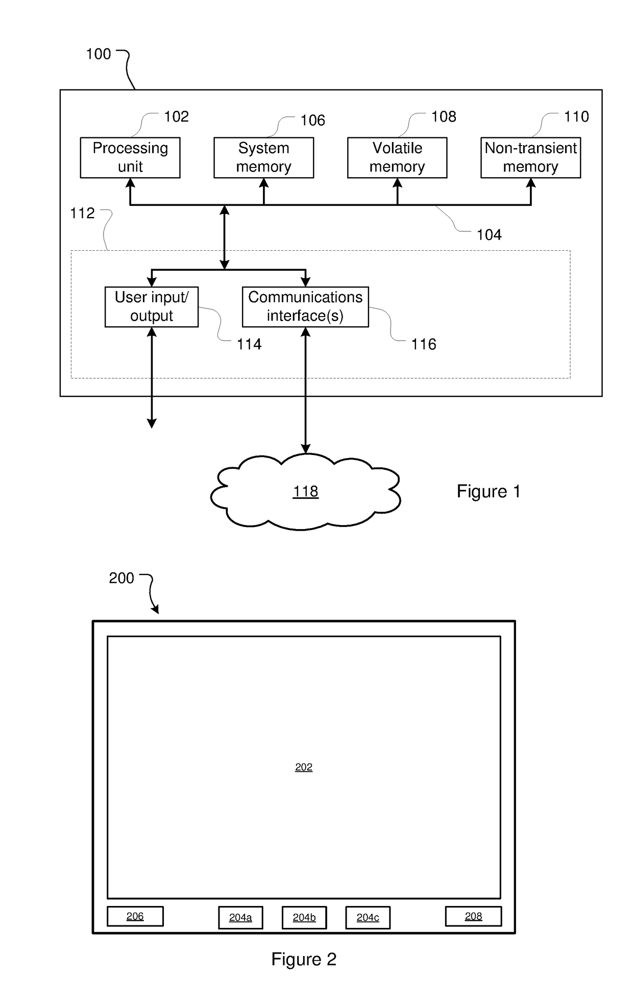
[0038]FIG. 1 provides a block diagram of one example of a computer processing system 100. System 100 as illustrated in FIG. 1 is a general-purpose computer processing system. It will be appreciated that FIG. 1 does not illustrate all functional or physical components of a computer processing system. For example, no power supply or power supply interface has been depicted, however system 100 will either carry a power supply or be configured for connection to a power supply (or both). It will also be appreciated that the particular type of computer p...


PUM


Abstract

Described herein is a computer implemented method for generating a calendar interface. The method includes determining a total time period value indicating a total time period to be displayed, determining a segment duration, determining an interval duration, calculating timeline coordinates defining a timeline extending from a foreground of the display to a background of the display and having a perspective appearance, and displaying a timeline in accordance with the timeline coordinates. The timeline coordinates define the timeline to have a plurality of segments, each segment representing a period of time within the total time period equal to the segment duration. Each segment is composed of a plurality of timeline intervals, each timeline interval representing a period of time within the total time period equal to the interval duration. Each segment has a display length, and wherein the display length of a segment representing an earlier period of time is longer than a display length of a segment representing a later period of time. A given segment travels in a direction that is re-entrant relative to a direction travelled by an adjacent segment.

Description

FIELD OF THE INVENTION[0001]The present disclosure relates to systems and methods for generating and displaying a calendar interface on an electronic device.BACKGROUND OF THE INVENTION[0002]Calendars allow users to view information such as dates, times, events, and time intervals.[0003]Increasingly, instead of (or as well as) relying on paper calendars people are viewing and managing calendar information on electronic devices such as computers and mobile phones.[0004]A problem with this, however, is that as more information is included and displayed calendars become visually complex. This can lead to users having difficulty in easily assessing the information being presented. This can be particularly problematic when viewing calendars on portable electronic devices with smaller screens, and is further exacerbated if a user attempts to view multiple calendars at the same time.[0005]Accordingly, it would be desirable to provide a calendar interface for an electronic device which prese...

Claims


Application Information

Patent Timeline
Patent Type & Authority Applications(United States)
IPC IPC(8): G06Q10/10
CPCG06F3/0481G06Q10/1093G06F3/04847G06Q10/109
Inventor MARTIN, BRUCE
Owner MRP SYST
Learn More