Vehicle headlamp device

a headlamp device and vehicle technology, applied in lighting and heating apparatus, television systems, instruments, etc., can solve the problems of inability to irradiate an area in front of the vehicle, inconvenient use of the vehicle headlamp device, and inability to achieve the goal

Active Publication Date: 2017-05-11
TOYOTA JIDOSHA KK
View PDF5 Cites 10 Cited by
  • Summary
  • Abstract
  • Description
  • Claims
  • Application Information

AI Technical Summary

Benefits of technology

[0010]According to the above embodiment, it is possible to provide a vehicle headlamp device that is able to correct an optical axis deviation by itself without using dedicated equipment.

Problems solved by technology

However, optical axis adjustment using a headlight tester requires dedicated adjusting equipment, and, in reality, a headlamp is used without adjusting an optical axis deviation that occurs in the headlamp.
Therefore, inconvenience may arise in a vehicle headlamp device that requires high accuracy in irradiation position.
For example, in a vehicle headlamp device, which is structured so as to be able to change a light distribution pattern as appropriate with the aim to, for example, improve visibility of an area in front of a vehicle, and perform glare protection for a pedestrian, an oncoming vehicle, and so on, it is not possible to irradiate an area in front of the vehicle in an appropriate light distribution pattern when an optical axis is deviated.
Thus, the aims may not be achieved.

Method used


Image

  • Vehicle headlamp device
  • Vehicle headlamp device
  • Vehicle headlamp device

Examples


Embodiment Construction

[0016]An embodiment of the invention is explained below with reference to the drawings.

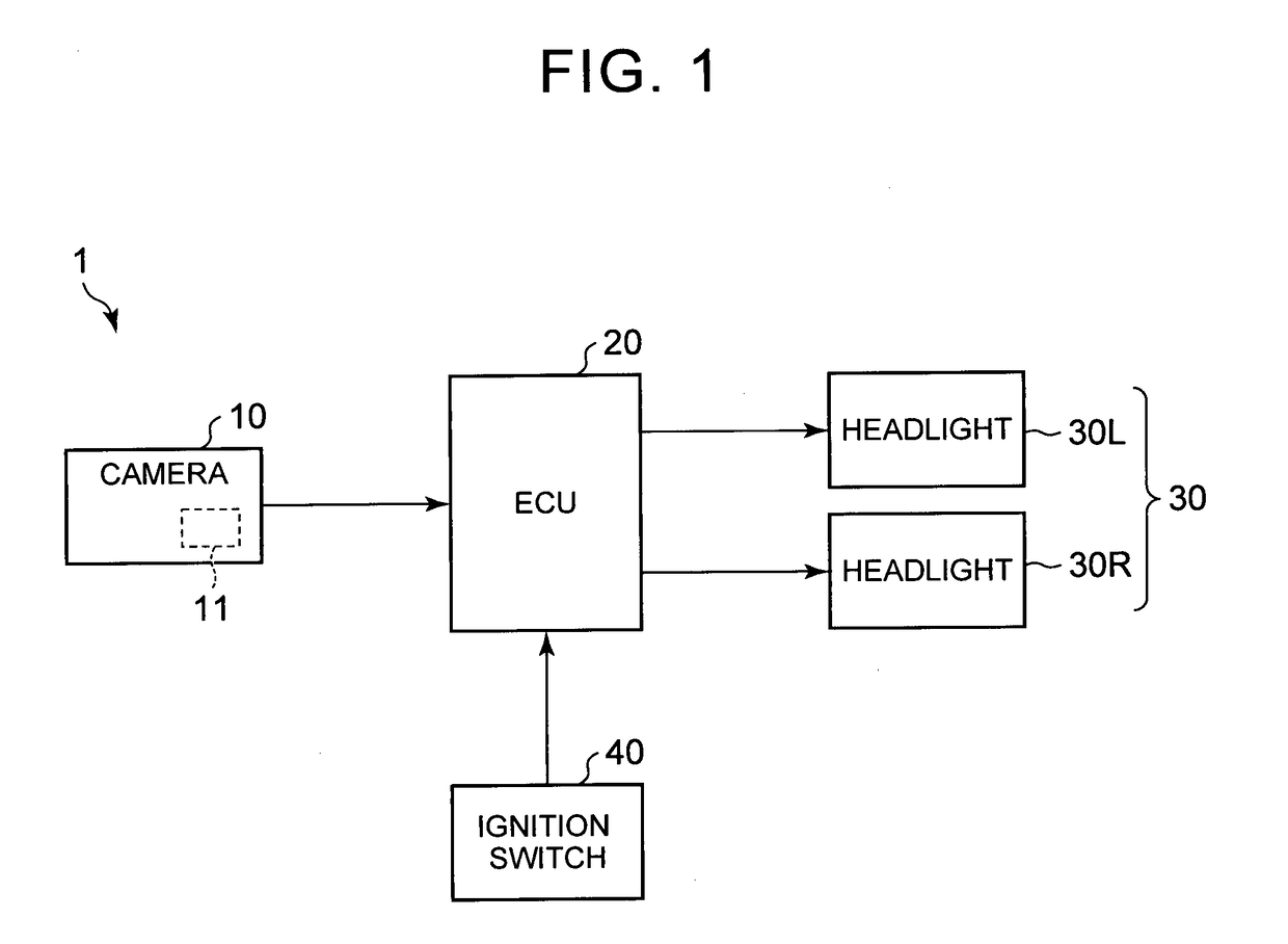
[0017]FIG. 1 is a structural view showing an example of a vehicle headlamp device 1 according to the embodiment.

[0018]The vehicle headlamp device 1 is mounted on a vehicle and includes a camera 10, an ECU 20, headlamps 30, an ignition switch 40, and so on.

[0019]Herein below, descriptions regarding directions (a longitudinal direction, a horizontal direction, and a vertical direction) are used as a longitudinal direction, a horizontal direction, and a vertical direction of a vehicle, respectively, unless otherwise specified.

[0020]The camera 10 is image-capturing means for capturing an image of an area in front of a vehicle, and includes an image-processing part 11. The camera 10 may be mounted at any position where the camera 10 is able to image an area in front of the vehicle. For example, the camera 10 may be arranged in a cabin in an upper part of a windshield in terms of protection against dust...


PUM


Abstract

A vehicle headlamp device includes headlamps, which are structured so as to be able to project or irradiate given patterns and given shapes without distortion on a given virtual surface in front of a vehicle from a left headlight and a right headlight, respectively, a camera that captures an image of the area in front of the vehicle, and a state detecting portion configured to detect distortion of the given patterns, which are projected or irradiated on an irradiated surface in front of the vehicle, relative to the given patterns projected or irradiated on the given virtual surface in front of the vehicle, based on the captured image, and also detect a state of the irradiated surface based on the distortion, and a correcting portion configured to correct a relative optical axis deviation between the left headlight and the right headlight.

Description

BACKGROUND OF THE INVENTION[0001]1. Field of the Invention[0002]The invention relates to a vehicle headlamp device.[0003]2. Description of Related Art[0004]A method for adjusting an optical axis of a headlight using a headlight tester is known (for example, Japanese Patent Application Publication No. 5-087686 (JP 5-087686 A)).[0005]However, optical axis adjustment using a headlight tester requires dedicated adjusting equipment, and, in reality, a headlamp is used without adjusting an optical axis deviation that occurs in the headlamp. Therefore, inconvenience may arise in a vehicle headlamp device that requires high accuracy in irradiation position.[0006]For example, in a vehicle headlamp device, which is structured so as to be able to change a light distribution pattern as appropriate with the aim to, for example, improve visibility of an area in front of a vehicle, and perform glare protection for a pedestrian, an oncoming vehicle, and so on, it is not possible to irradiate an are...

Claims


Application Information

Patent Timeline
Patent Type & Authority Applications(United States)
IPC IPC(8): B60Q1/08G01M11/06G06K9/00H04N7/18F21S8/10
CPCB60Q1/085H04N7/183F21S48/1757B60Q2300/05G01M11/068G01M11/064G06K9/00791B60Q1/08B60Q2400/50B60Q2200/38B60Q2400/40F21S41/675G06V20/56
Inventor ASAOKA, KAZUYASHIRAKI, NOBUYUKIHIRATSUKA, SHIGEYOSHIKOJIMA, SHIN-ICHITSUKADA, TOSHIHIKOSHIMAOKA, KEIICHIHIGUCHI, KAZUNORI
Owner TOYOTA JIDOSHA KK
Why Eureka
Try Eureka