Wet dual plate clutch with levers in the wet chamber

Active Publication Date: 2017-05-18
SCHAEFFLER TECH AG & CO KG
View PDF9 Cites 1 Cited by
  • Summary
  • Abstract
  • Description
  • Claims
  • Application Information

AI Technical Summary

Benefits of technology

[0014]A particular advantage of the present invention is that a conventional, existing dual clutch, for example a dry dual clutch, can be exchanged for a wet dual clutch according to the present invention with only a little modification effort and expense for the customer. The dual clutch according to the present invention is actuated by means of a lever mechanism integrated into the wet chamber housing. The clutch friction devices of both a drive clutch and an auxiliary power take-off clutch are located in a sealed area known as the wet chamber, which is enclosed by the wet chamber housing and is sealed fluid-tight. The dual clutch can therefore be designed and used advantageously as a wet clutch, so that with the same or only slightly greater construction space compared to known dual clutches according to the genre, a large volume of frictional heat can be absorbed and removed. In addition, the dual clutch according to the present invention is especially well suited for transmitting high maximum torques.
[0015]The drive clutch and the auxiliary power take-off clutch are actuatable independently of one another; in particular they are engageable simultaneously. The dual clutch according to the present invention is thus especially well suited for use in agricultural machinery such as tractors.
[0016]Advantageous embodiments of the invention will be explained in greater detail below.
[0017]According to one embodiment of the present invention, the dual clutch can have a clutch housing that supports the lever mechanisms. A

Problems solved by technology

It is disadvantageous that in such known dry dual clutches the maximum thermal absorptive capacity of the clutches and the maximum thermal capacity of the clutch linings as a rule is quickly reachable, in particular when transmitting high torques.
Increasing the transmissible torque while keeping the construction size the same is therefore limited.
In the critical load range, high wear of the friction linings and a resulti

Method used


Image

  • Wet dual plate clutch with levers in the wet chamber
  • Wet dual plate clutch with levers in the wet chamber
  • Wet dual plate clutch with levers in the wet chamber

Examples


Example

[0046]The figures are merely schematic in nature, and serve only to aid in understanding the present invention. The same elements are identified by the same reference numerals. Details of the different embodiments can be combined with one another.

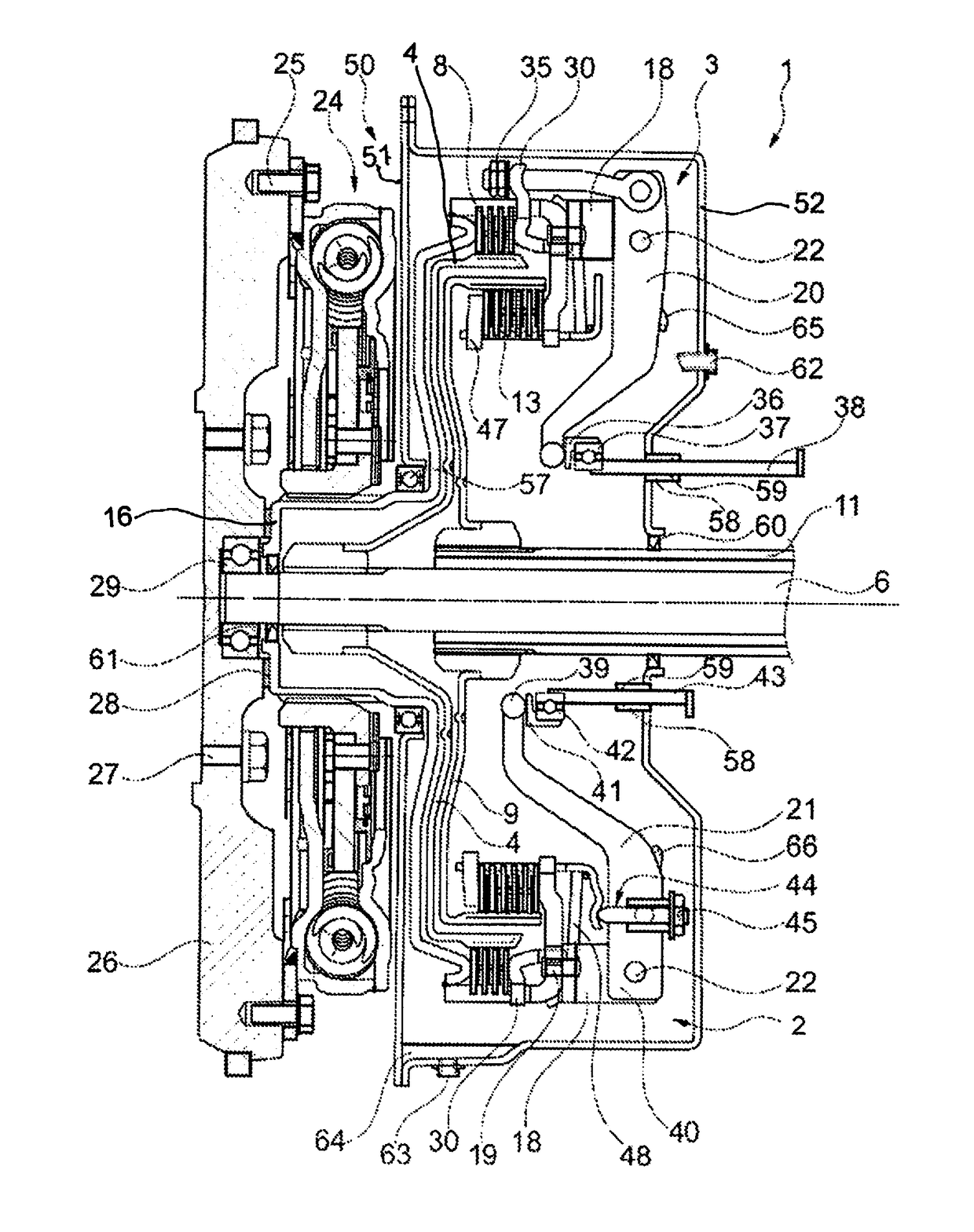
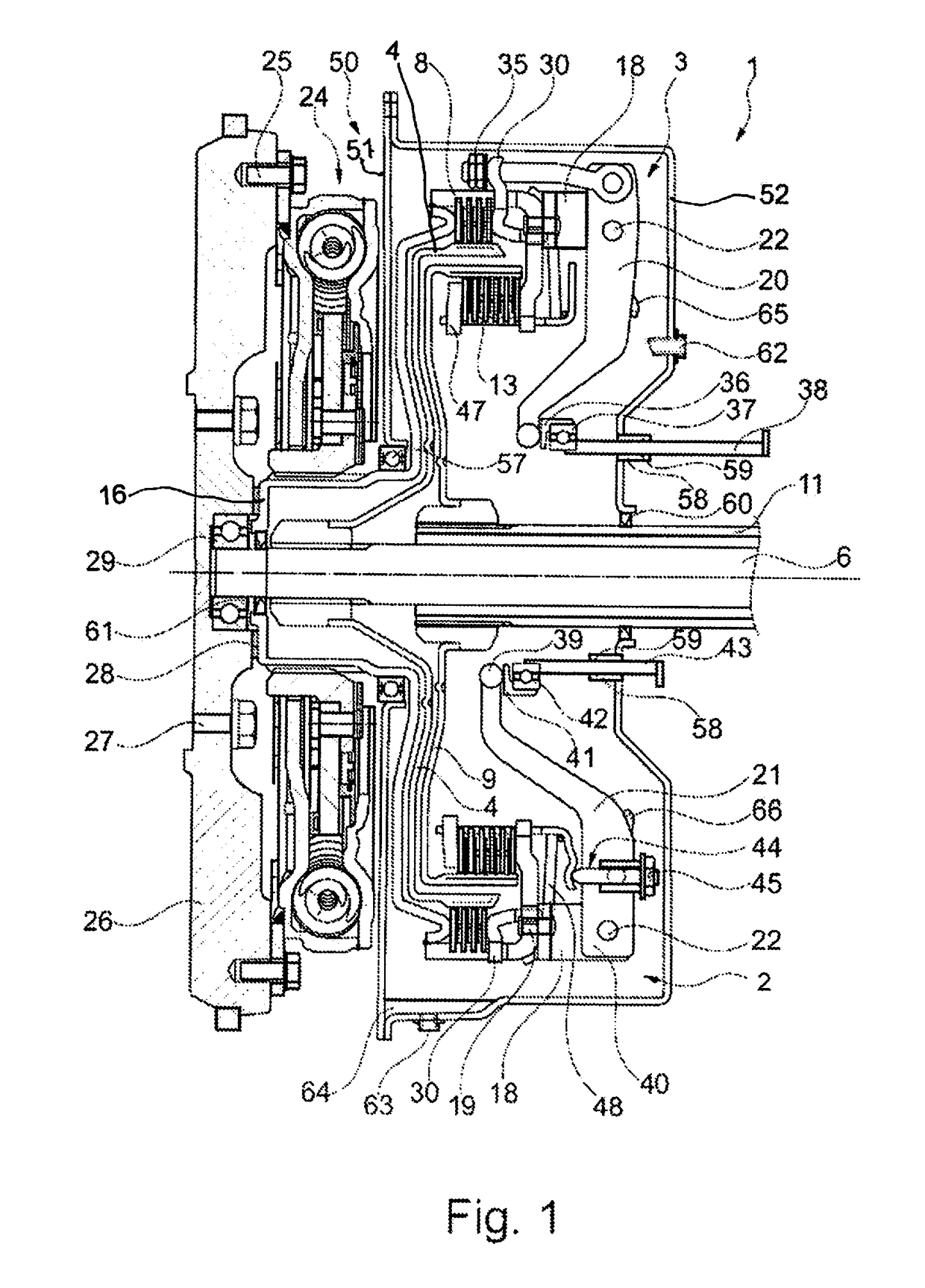
[0047]FIG. 1 shows a dual clutch 1 according to the present invention. It includes a first, radially inner clutch unit 2, in the present exemplary embodiment a drive shaft clutch 2, and a second, radially outer clutch unit 3, in the present exemplary embodiment a power take-off shaft clutch 3. The dual clutch 1 is designed as a wet clutch.

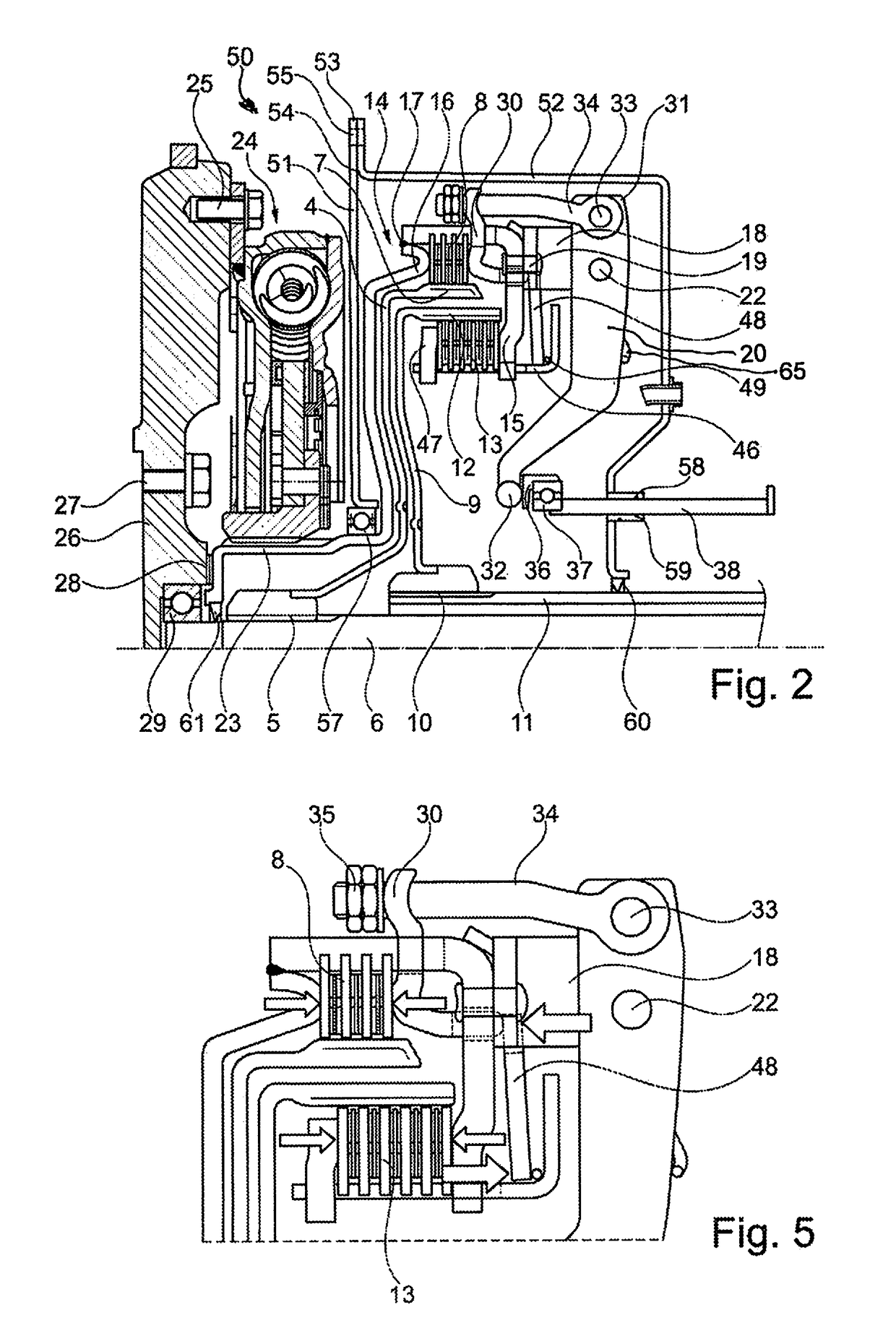
[0048]Referring to FIG. 2, power take-off shaft clutch 3 has a disk carrier 4, that is non-rotatably positioned on a power take-off shaft 6 by means of power take-off shaft toothed connection 5. The disk carrier 4 is an essentially bell-shaped formed sheet metal part, for example a deep drawn part, and carries a disk pack 8 on the outer side of its radially outer edge segment 7.

[0049]The drive shaft clutch...


PUM


Abstract

A multi-plate dual clutch for coupling a motor vehicle engine to a drive shaft of a motor vehicle transmission and to an auxiliary power take-off output shaft of the motor vehicle. The dual clutch includes a drive clutch for coupling the motor vehicle engine with the drive shaft, and an auxiliary power take-off clutch for coupling the motor vehicle engine with the auxiliary output shaft. The drive clutch and the auxiliary power take-off clutch can each to be operated independently of one another by a separate lever mechanism. The dual clutch includes a wet chamber housing in which the drive clutch, the auxiliary power take-off clutch, and the respective lever mechanisms are accommodated in fluid-tight relationship.

Description

CROSS-REFERENCE TO RELATED APPLICATIONS[0001]This application is the U.S. national phase patent application under 35 U.S.C. §371 of International Patent Application Serial No. PCT / DE2015 / 200352, having an international filing date of 9 Jun. 2015, and designating the United States, which claims priority based upon German Patent Application No. DE 10 2014 212 416.6, filed on 27 Jun. 2014, the entire contents of each of which applications are hereby incorporated by reference herein to the same extent as if fully rewritten.BACKGROUND OF THE INVENTION[0002]Field of the Invention[0003]The present invention relates to a dual clutch, in particular a multi-plate dual clutch for coupling a drive shaft of a motor vehicle engine to a transmission shaft of a motor vehicle transmission and / or an auxiliary output shaft of an auxiliary power take-off of the motor vehicle, in particular a power take-off shaft. The dual clutch includes a drive clutch for coupling the motor vehicle engine with the tra...

Claims


Application Information

Patent Timeline
IPC IPC(8): F16D13/38F16D23/12B60K17/02B60K17/28F16D13/52F16D21/06
CPCF16D13/385F16D13/52F16D21/06B60K17/02F16D2023/126F16D23/12F16D2021/0676F16D2300/0214B60K17/28F16D2300/12F16D13/74
Inventor FILSINGER, ANDREASWEYDMANN, PATRICKGANDER, GERHARDOBITZ, ALEXAMDER
Owner SCHAEFFLER TECH AG & CO KG
Why Eureka
Try Eureka