Cooling circuit for a multi-wall blade

a cooling circuit and multi-wall blade technology, applied in the field of turbine systems, can solve the problems of low cooling effectiveness internal channels exposed to very high heat loads, components to fail, and near wall cooling channels

Active Publication Date: 2017-06-22
GENERAL ELECTRIC CO
View PDF7 Cites 26 Cited by
  • Summary
  • Abstract
  • Description
  • Claims
  • Application Information

AI Technical Summary

Problems solved by technology

During operation of a gas turbine system, various components in the system, such as turbine blades, are subjected to high temperature flows, which can cause the components to fail.
At the tip of a multi-wall blade, the near wall cooling channels and low cooling effectiveness internal channels are exposed to very high heat loads.

Method used


Image

  • Cooling circuit for a multi-wall blade
  • Cooling circuit for a multi-wall blade
  • Cooling circuit for a multi-wall blade

Examples


Embodiment Construction

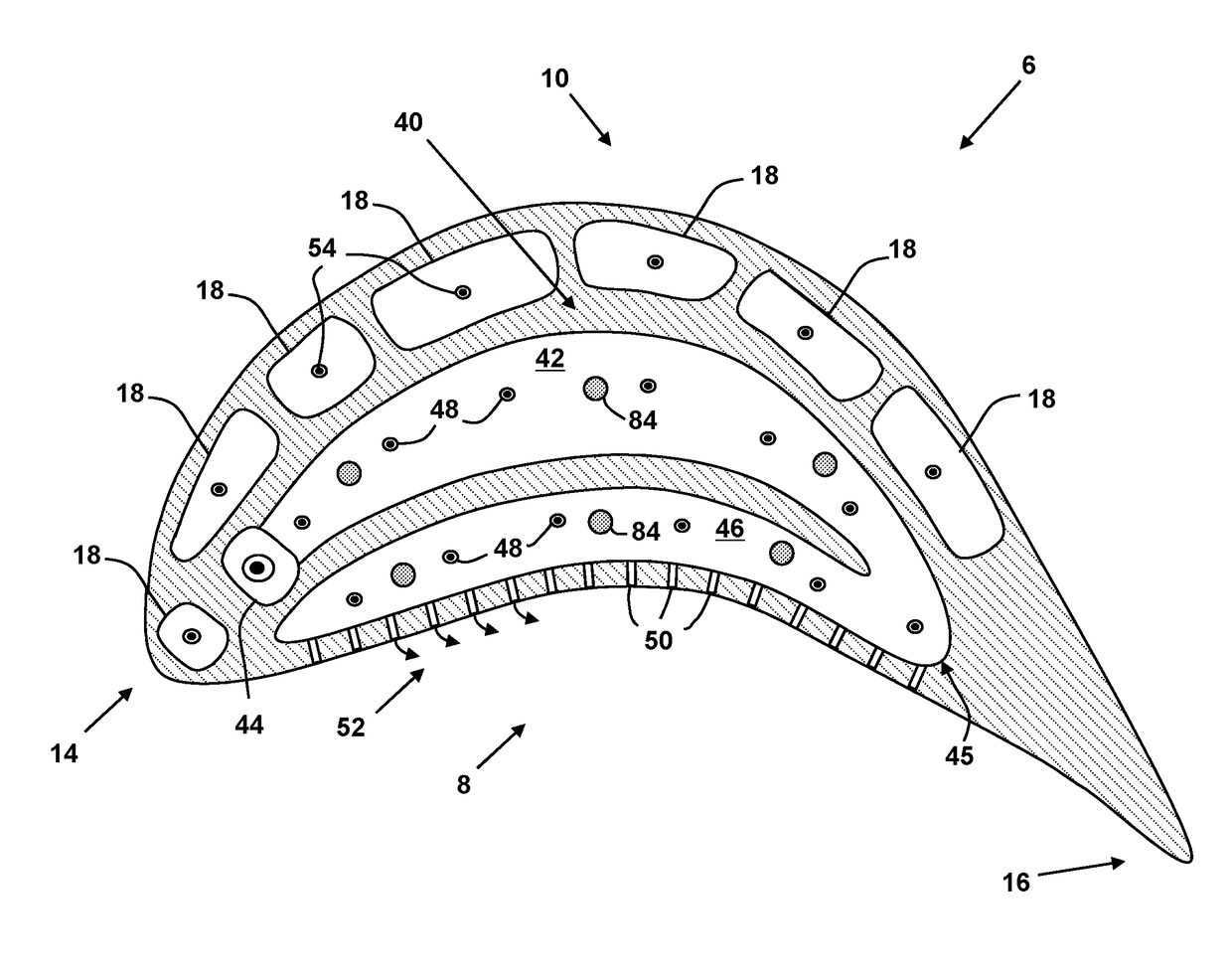
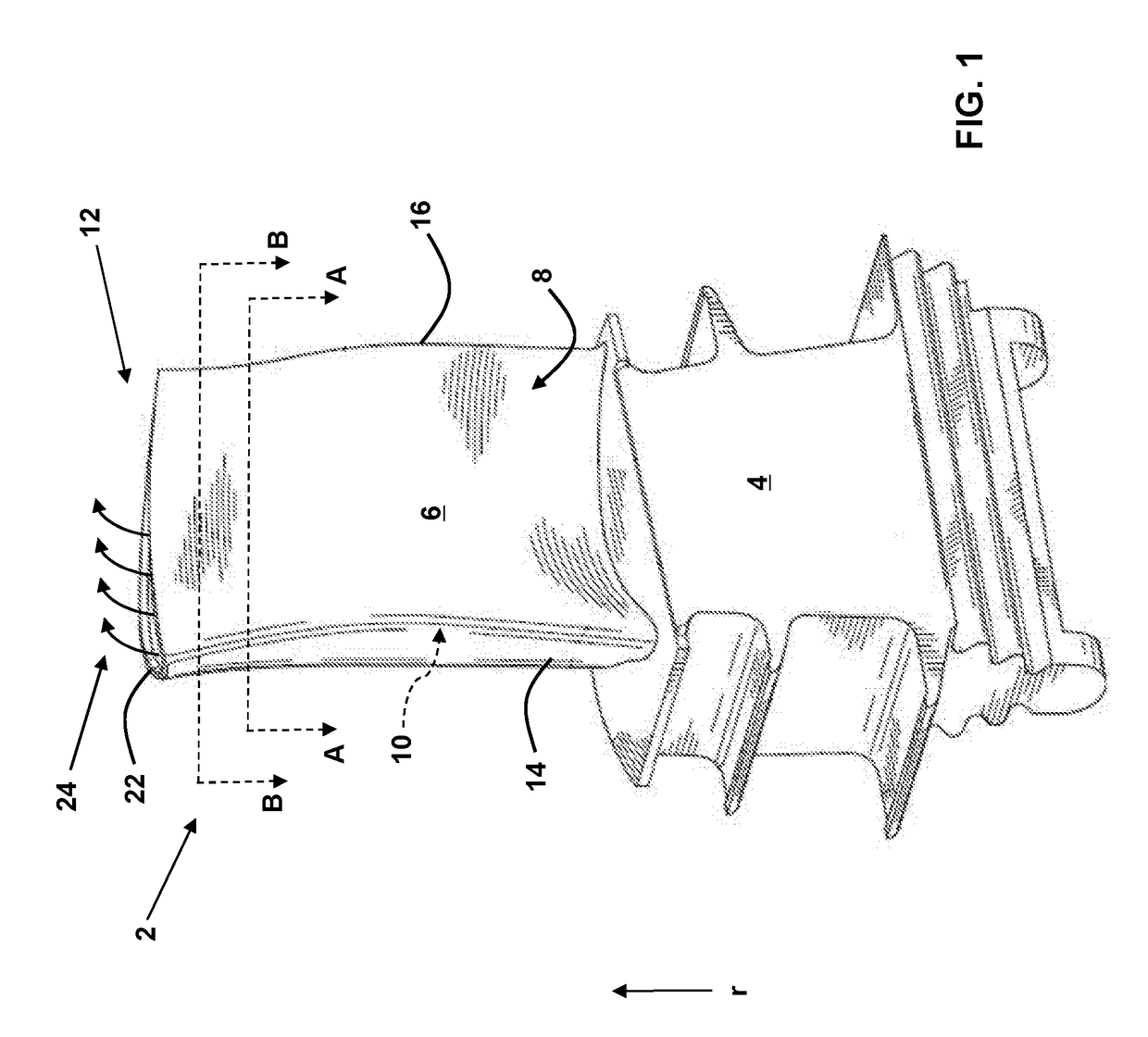
[0020]In the Figures, for example in FIG. 9, the “A” axis represents an axial orientation. As used herein, the terms “axial” and / or “axially” refer to the relative position / direction of objects along axis A, which is substantially parallel with the axis of rotation of the turbomachine (in particular, the rotor section). As further used herein, the terms “radial” and / or “radially” refer to the relative position / direction of objects along an axis (r), which is substantially perpendicular with axis A and intersects axis A at only one location. Additionally, the terms “circumferential” and / or “circumferentially” refer to the relative position / direction of objects along a circumference (c) which surrounds axis A but does not intersect the axis A at any location.

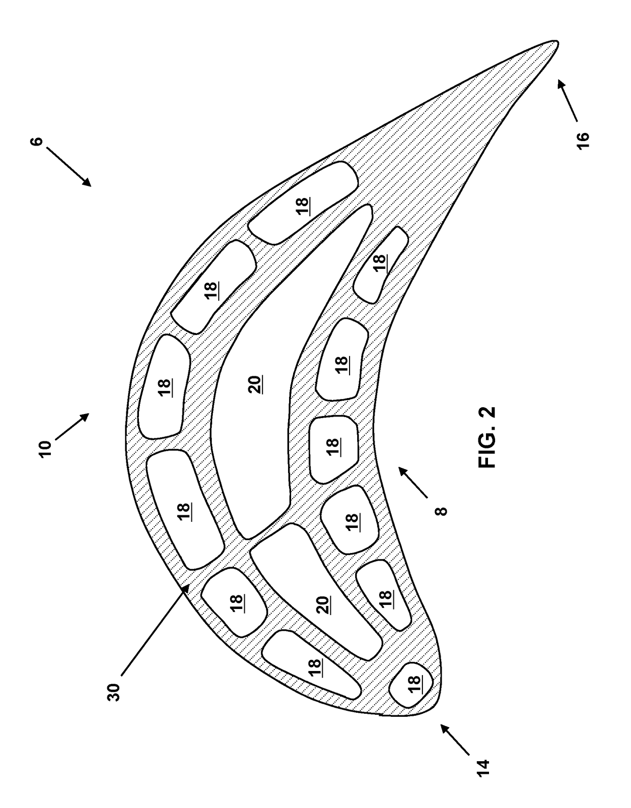
[0021]As indicated above, the disclosure relates generally to turbine systems, and more particularly, to a cooling circuit for cooling a tip area of a multi-wall blade.

[0022]According to embodiments, the cooling circuit is configu...


PUM


Abstract

A cooling system according to an embodiment includes: a serpentine cooling circuit, the serpentine cooling circuit including a first leg extending in a first direction, a second leg extending in a second direction, and a turn fluidly coupling the first leg and the second leg; and an air feed cavity for supplying cooling air to the serpentine cooling circuit; wherein the first leg of the serpentine cooling circuit extends radially outward from and at least partially covers at least one central plenum of a multi-wall blade, and wherein the second leg of the serpentine cooling circuit extends radially outward from and at least partially covers a first set of near wall cooling channels of the multi-wall blade.

Description

CROSS-REFERENCE TO RELATED APPLICATIONS[0001]This application is related to co-pending U.S. application Ser. Nos.: ______, GE docket numbers 282168-1, 282169-1, 282171-1, 282174-1, 283464-1, 283467-1, 283463-1, and 284160-1, all filed on ______.BACKGROUND OF THE INVENTION[0002]The disclosure relates generally to turbine systems, and more particularly, to a cooling circuit for a tip area of a multi-wall blade.[0003]Gas turbine systems are one example of turbomachines widely utilized in fields such as power generation. A conventional gas turbine system includes a compressor section, a combustor section, and a turbine section. During operation of a gas turbine system, various components in the system, such as turbine blades, are subjected to high temperature flows, which can cause the components to fail. Since higher temperature flows generally result in increased performance, efficiency, and power output of a gas turbine system, it is advantageous to cool the components that are subje...

Claims


Application Information

Patent Timeline
Patent Type & Authority Applications(United States)
IPC IPC(8): F01D5/18F02C3/04
CPCF01D5/187F02C3/04F05D2250/185F05D2220/32F05D2240/307F05D2240/305F05D2260/205F01D5/186
Inventor SMITH, AARON EZEKIELFOSTER, GREGORY THOMASWEBER, DAVID WAYNEWEBER, JOSEPH ANTHONY
Owner GENERAL ELECTRIC CO
Why Eureka
Try Eureka