
Resonant frequency tunable antenna

Inactive Publication Date: 2017-06-29
LG ELECTRONICS INC
View PDF14 Cites 4 Cited by
  • Summary
  • Abstract
  • Description
  • Claims
  • Application Information

AI Technical Summary

Benefits of technology

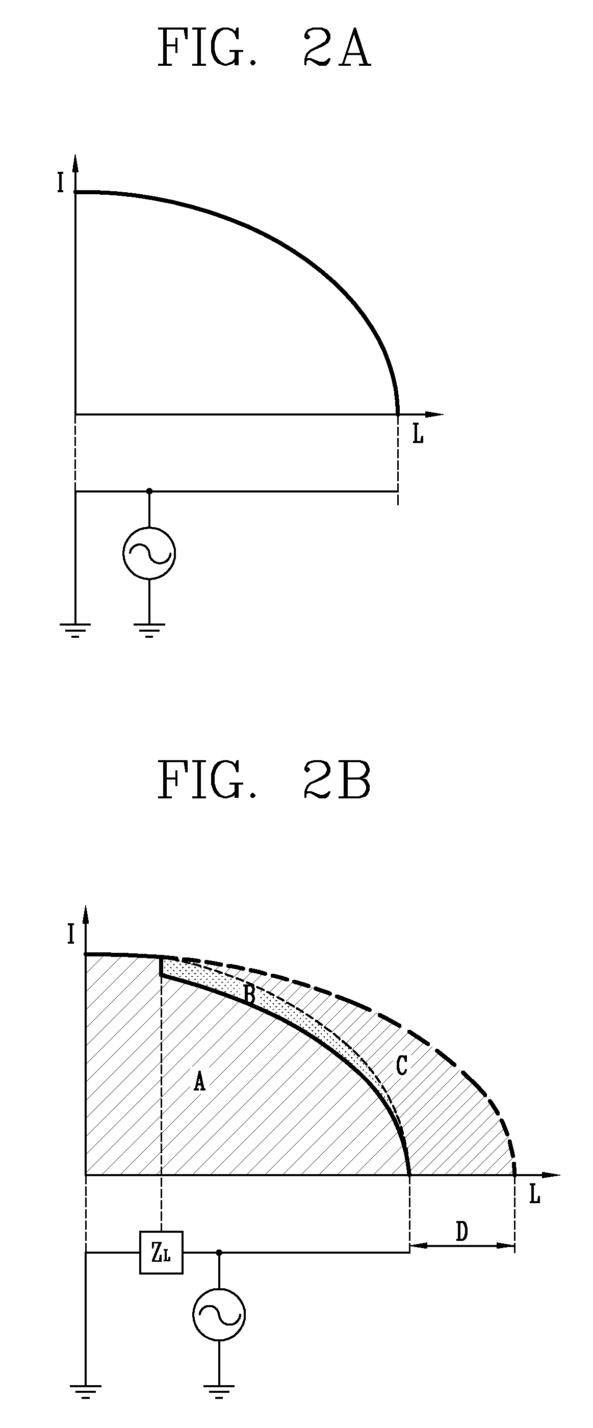
The present invention provides a resonant frequency tunable antenna that can control the frequency range of an antenna through a frequency tuning technology. The antenna includes a main ground part, a feeding part, and a variable ground part. The impedance control circuit can selectively control the impedance of the feeding part or the variable ground part using inductors or capacitors. The antenna can achieve a low resonant frequency by increasing the inductance and a high resonant frequency by decreasing the capacitance. The antenna can be used in a mobile terminal to achieve a wide frequency range and minimize the input impedance difference between the lowest and highest frequencies.

Problems solved by technology

Meanwhile, with a global introduction of 4G-LTE systems, limited frequency resources are occupied by each communication operator to supply services, and the frequency band is different for each communication operator.
However, in a country with a broad area, it is difficult for a single operator to service all the regions of the nation by using its own base station.
However, in the case of a mobile communication terminal in which portability is emphasized, since the space for designing the antenna is continuously reduced for miniaturization, it is not easy to design the antenna to include all the wide frequency range.

Method used


Image

  • Resonant frequency tunable antenna
  • Resonant frequency tunable antenna
  • Resonant frequency tunable antenna

Examples


Embodiment Construction

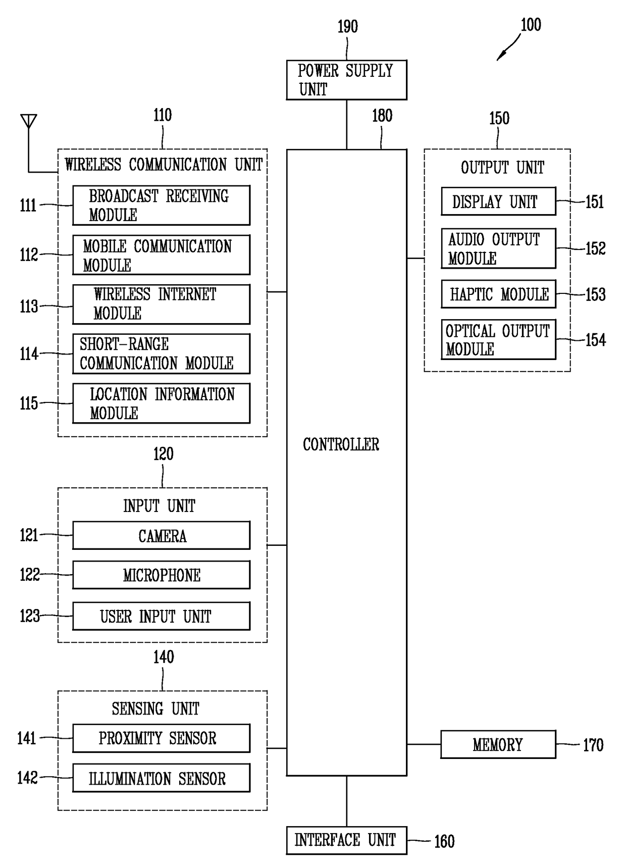
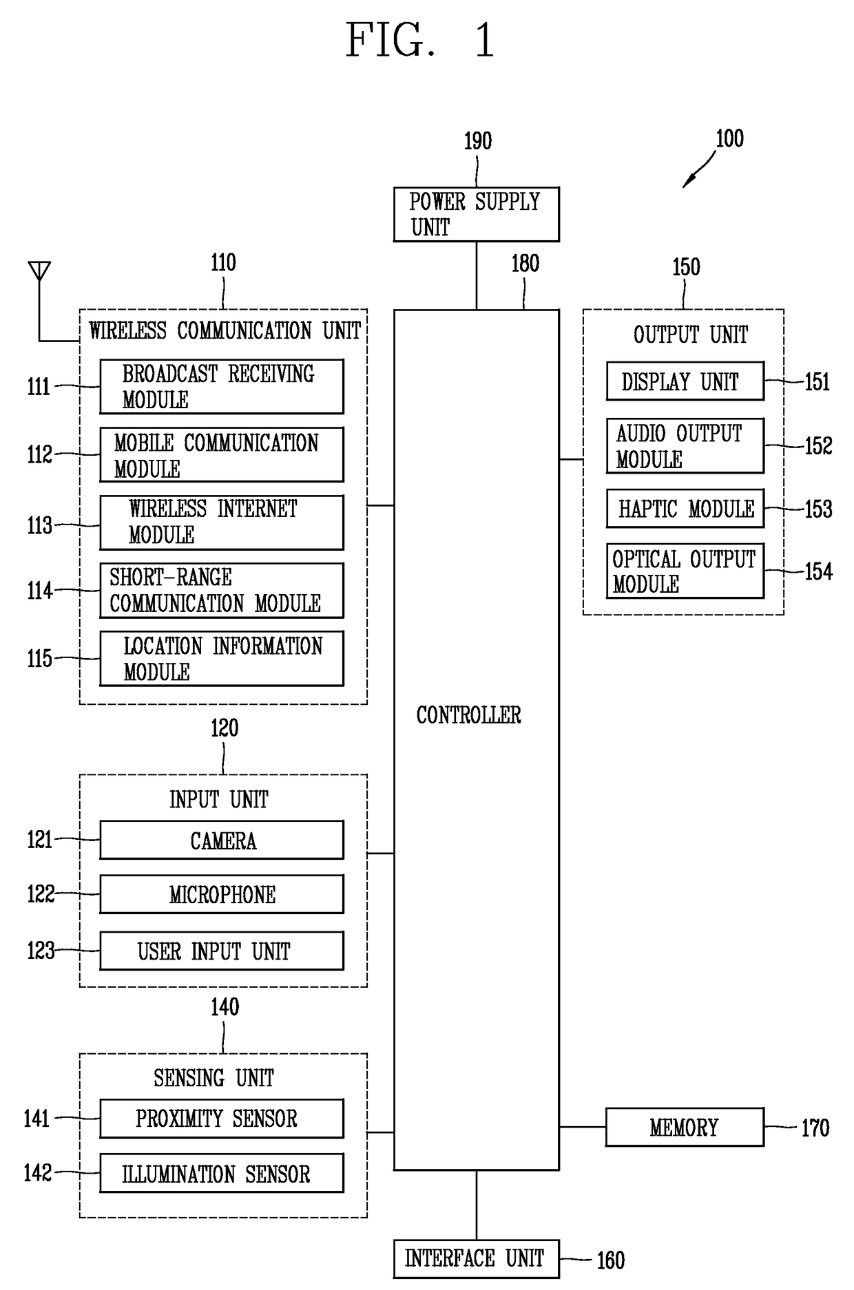
[0048]Description will now be given in detail according to exemplary embodiments disclosed herein, with reference to the accompanying drawings. For the sake of brief description with reference to the drawings, the same or equivalent components may be provided with the same or similar reference numbers, and description thereof will not be repeated. In general, a suffix such as “module” and “unit” may be used to refer to elements or components. Use of such a suffix herein is merely intended to facilitate description of the specification, and the suffix itself is not intended to give any special meaning or function. In the present disclosure, that which is well-known to one of ordinary skill in the relevant art has generally been omitted for the sake of brevity. The accompanying drawings are used to help easily understand various technical features and it should be understood that the embodiments presented herein are not limited by the accompanying drawings. As such, the present disclo...


PUM


Abstract

The present invention relates to a resonant frequency tunable antenna, and may provide a resonant frequency tunable antenna which comprises: a first ground part; a power supply part connected in the longitudinal direction of the antenna from the first power supply part; and a second ground part connected in the longitudinal direction of the antenna from the power supply part, wherein the second ground part is a variable ground part, the second ground part and the power supply part are connected by a switch, and the switch is connected to a common terminal which is grounded, so that the second ground part and the power supply part are linked and controlled.

Description

TECHNICAL FIELD[0001]The present disclosure relates to a resonant frequency tunable antenna, and more particularly, a resonant frequency tunable antenna, capable of controlling a resonant frequency for using a multiband in a mobile communication system.BACKGROUND ART[0002]Terminals may be divided into mobile / portable terminals and stationary terminals according to their mobility. Also, the mobile terminals may be classified into handheld terminals and vehicle mount terminals according to whether or not a user can directly carry.[0003]Mobile terminals have become increasingly more functional. Examples of such functions include data and voice communications, capturing images and video via a camera, recording audio, playing music files via a speaker system, and displaying images and video on a display. Some mobile terminals include additional functionality which supports game playing, while other terminals are configured as multimedia players. More recently, mobile terminals have been ...

Claims


Application Information

Patent Timeline
IPC IPC(8): H01Q5/335H01Q9/04H01Q1/48H01Q1/24
CPCH01Q5/335H01Q1/48H01Q9/0421H01Q1/243H01Q1/242H01Q9/42H01Q5/328
Inventor NOH, JAEWONPAEK, KYUNGCHEOL
Owner LG ELECTRONICS INC
Learn More