Anisotropic optical film

an optical film and anisotropic technology, applied in the field of anisotropic optical films, can solve the problems of achieve the effects of suppressing td brightness rapid change and glare generation, excellent display characteristics, and high linear transmittan

Active Publication Date: 2017-07-06
TOMOEGAWA CO LTD
View PDF5 Cites 16 Cited by
  • Summary
  • Abstract
  • Description
  • Claims
  • Application Information

AI Technical Summary

Benefits of technology

[0010]Therefore, the present invention has been made in order to solve the problem mentioned above, and an object of the invention is to provide an anisotropic optical film which has a high linear transmittance in a non-diffusion region, and has a large diffusion region in the MD direction and the TD direction, thereby making it possible to solve problems such as a rapid change in brightness and generation of glare.
[0011]The inventors have found, as a result of earnestly carrying out studies in order to solve the problem mentioned above, that found that an anisotropic light diffusion layer that has a columnar structure and an anisotropic light diffusion layer including a pillar region where a cross-sectional shape has a lower aspect ratio than a tabular structure, and a higher aspect ratio than the columnar structure are stacked, thereby making it possible to achieve a balance between a high linear transmittance in the non-diffusion region and a large diffusion region in the MD direction and the TD direction, and achieved the present invention on the basis of the finding.
[0026]According to the present invention, the anisotropic light diffusion layer including pillar regions with an aspect ratio of less than 2 and the anisotropic light diffusion layer including pillar regions with an aspect ratio of 2 or more and 20 or less can be stacked to provide an anisotropic optical film which achieves a balance between a high linear transmittance in a non-diffusion region and large diffusion regions in the MD direction and the TD direction. Accordingly, when the anisotropic optical film is used as a diffusion film of a display panel, it becomes possible to provide an anisotropic optical film which can, while keeping excellent display characteristics (e.g., brightness and contrast), suppress the rapid change in brightness and the generation of glare.

Problems solved by technology

However, the anisotropic optical film described in JP2012-141593 A has, because of the use of the anisotropic light diffusion layer of tabular structure, a diffusion width expanded in the MD direction, but still fails to have a diffusion width extended insufficiently in the TD direction, and has the problem of being likely to produce a rapid change in brightness in the TD direction and produce glare.

Method used


Image

  • Anisotropic optical film
  • Anisotropic optical film
  • Anisotropic optical film

Examples


example 1

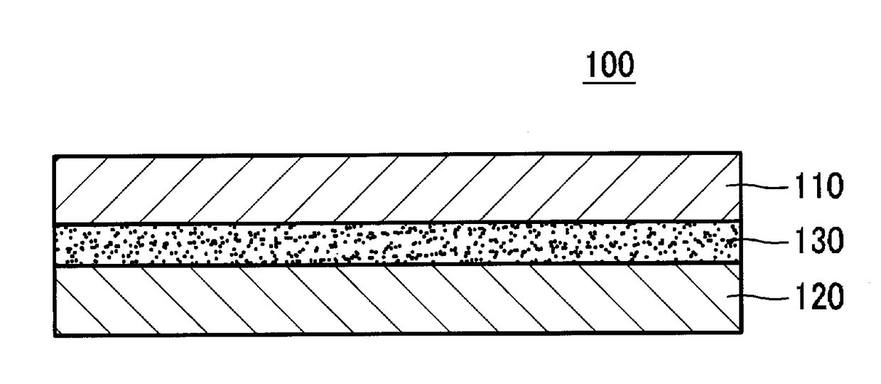
[0189]On the entire peripheral edge of a PET film (from Toyobo Co., Ltd., Trade Name: A4300) of 100 μm in thickness, a partition of 0.03 mm in height was formed from a curable resin with the use of a dispenser. This space within the wall was filled with the following photo-curable resin composition, and covered with a PET film.[0190]silicone urethane acrylate (Refractive Index: 1.460, Weight Average Molecular Weight: 5,890) 20 parts by weight (from RAHN, Trade Name: 00-225 / TM18)

Neopentyl Glycol Diacrylate (Refractive Index: 1.450) 30 parts by weight

(from Daicel Cytec, Inc., Trade Name Ebecryl 145)[0191]EO Adduct Diacrylate of Bisphenol A (Refractive Index: 1.536) 15 parts by weight

(from Daicel Cytec, Inc., Trade Name Ebecyl 150)[0192]Phenoxyethylacrylate (Refractive Index: 1.518) 40 parts by weight (from Kyoeisha Chemical Co., Ltd., Trade Name: Light Acrylate PO-A)[0193]2,2-dimethoxy-1,2-diphenylethane-1-on 4 parts by weight

(from BASF, Trade Name: Irgacure 651)

[0194]The liquid film ...

example 2

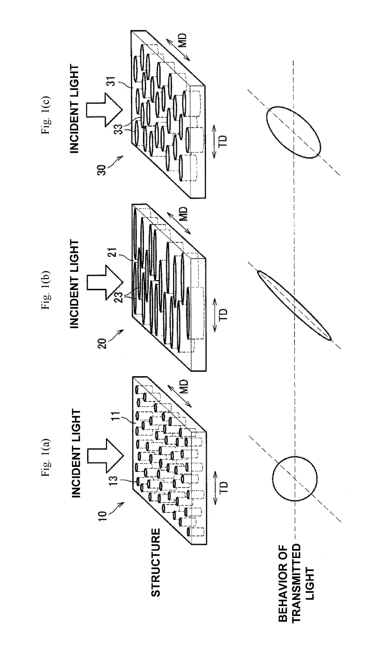
[0197]In the same way as in Example 1 except for the use of a directional diffusion element for adapting the aspect ratio of transmitted UV light rays to 8, an anisotropic optical film according to Example 2 was obtained. Tables 1 and 2 show the sizes of the pillar structures for each anisotropic light diffusion layer in the anisotropic optical film, and the evaluation results of an optical characteristics of the anisotropic optical film.

example 3

[0198]In the same way as in Example 1 except for the use of a directional diffusion element for adapting the aspect ratio of transmitted UV light rays to 16, an anisotropic optical film according to Example 3 was obtained. Tables 1 and 2 show the sizes of the pillar structures for each anisotropic light diffusion layer in the anisotropic optical film, and the evaluation results of an optical characteristics of the anisotropic optical film.


PUM

PropertyMeasurementUnit
diameteraaaaaaaaaa
diameteraaaaaaaaaa
diameteraaaaaaaaaa

Abstract

In an anisotropic optical film including two or more anisotropic light diffusion layers where a linear transmittance varies depending on an incident light angle, each of the anisotropic light diffusion layers has a matrix region and a plurality of pillar regions that differ in refractive index from the matrix region, at least two types of anisotropic light diffusion layers (a) and (b) that differ in aspect ratio between a short diameter and a long diameter at a cross section perpendicular to an orientation direction of the pillar regions are used as the anisotropic light diffusion layers, the aspect ratio between the short diameter and the long diameter in the pillar regions is made less than 2 in the anisotropic light diffusion layer (a), and the aspect ratio between the short diameter and the long diameter in the pillar regions is made 2 or more and 20 or less in the anisotropic light diffusion layer (b).

Description

BACKGROUND OF THE INVENTION[0001]The present invention relates to an anisotropic optical film which changes the diffusibility of transmitted light depending on the incident light angle.[0002]Members that have light diffusibility (light diffusion members) are used for lighting fixtures and building materials, as well as in display devices. The display devices include, for example, liquid crystal display devices (LCD) and organic electroluminescence elements (organic EL). The light diffusion mechanisms of the light diffusion members include scattering by asperity formed at the surfaces (surface scattering), scattering due to a refractive index difference between a matrix resin and microparticles dispersed therein (internal scattering), and both surface scattering and internal scattering. However, these light diffusion members generally have isotropic diffusion performance, and even when the incident light angles are somewhat changed, the diffusion characteristics of transmitted light ...

Claims


Application Information

Patent Timeline
Patent Type & Authority Applications(United States)
IPC IPC(8): G02B5/02G02F1/1335B05D7/04B29D11/00B05D5/06B05D3/06
CPCG02B5/0257B05D5/06B05D3/06B05D7/04B29K2033/08G02B5/0278G02B5/0268G02F1/133504B29K2667/003B29D11/00798G02B5/0236G02B5/02
Inventor SAKANO, TSUBASASUGIYAMA, MASAHIDE
Owner TOMOEGAWA CO LTD
Why Eureka
Try Eureka