
An Ultrashort Pulse Optical Limiter Based on Optical Kerr Effect

A technology of optical Kerr effect and ultrashort pulse, which is applied to lasers, laser components, phonon exciters, etc., can solve the problem of unsuitable design and manufacture of broadband limiting devices, the inability to achieve ultra-low limiting threshold output, and the inability to Ultra-short pulse limiting protection and other issues, to achieve the effect of wide spectral range, large dynamic range of applicable energy, and simple structure

Inactive Publication Date: 2016-08-17
XI AN JIAOTONG UNIV
View PDF4 Cites 0 Cited by
  • Summary
  • Abstract
  • Description
  • Claims
  • Application Information

AI Technical Summary

Problems solved by technology

It is difficult for the existing optical limiting technology to meet the above requirements at the same time. For example, the response speed of the optical limiter based on nonlinear scattering is generally slow, and the required pulse energy is generally large, which cannot achieve limit protection for ultrashort pulses; Although the optical limiter with linear refraction or self-focusing effect can be applied to ultrashort pulse lasers, it often has a high limiting threshold and cannot achieve ultra-low limiting threshold output; the optical limiter based on nonlinear absorption often affects the incident Optical wavelength is selective, not suitable for the design and manufacture of broadband limiting devices

Method used


Image

  • An Ultrashort Pulse Optical Limiter Based on Optical Kerr Effect
  • An Ultrashort Pulse Optical Limiter Based on Optical Kerr Effect
  • An Ultrashort Pulse Optical Limiter Based on Optical Kerr Effect

Examples


Embodiment Construction

[0026] The present invention will be further described in detail below in conjunction with specific embodiments, which are explanations of the present invention rather than limitations.

[0027] see figure 1 , the present invention includes a polarizer 1, a first quarter-wave plate 2, a first lens 3, a quartz cuvette 4, a second lens 5, and a second quarter-wave plate arranged in sequence along the incident light direction plate 6, analyzer 7, aperture 8 and detector 9, and the long-axis direction of the first quarter-wave plate 2 is orthogonal to the second quarter-wave plate 6, and the analyzer of the polarizer 7 The direction is parallel to the polarizing direction of the polarizer 1 .

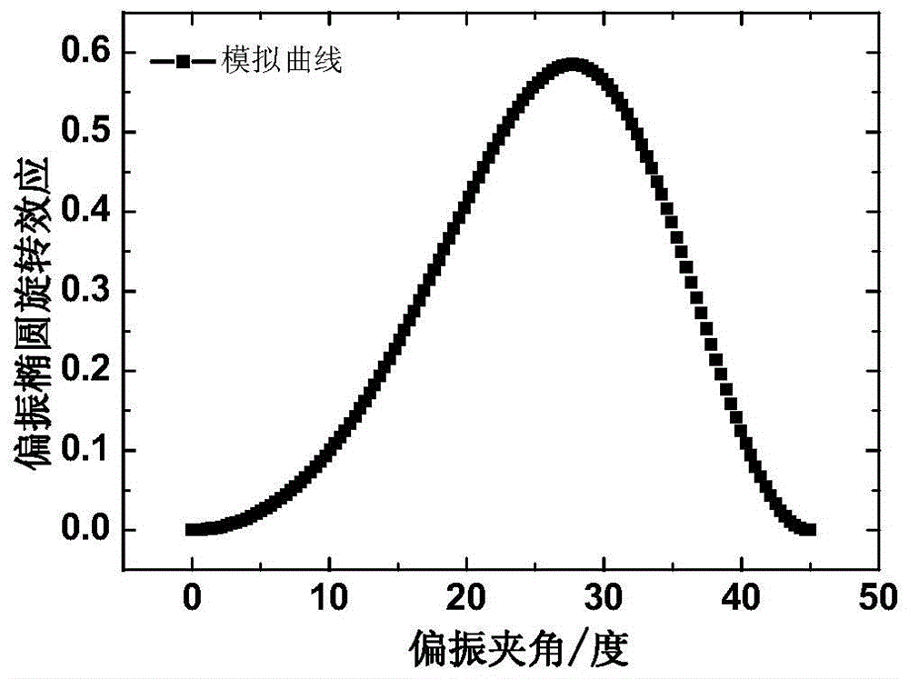
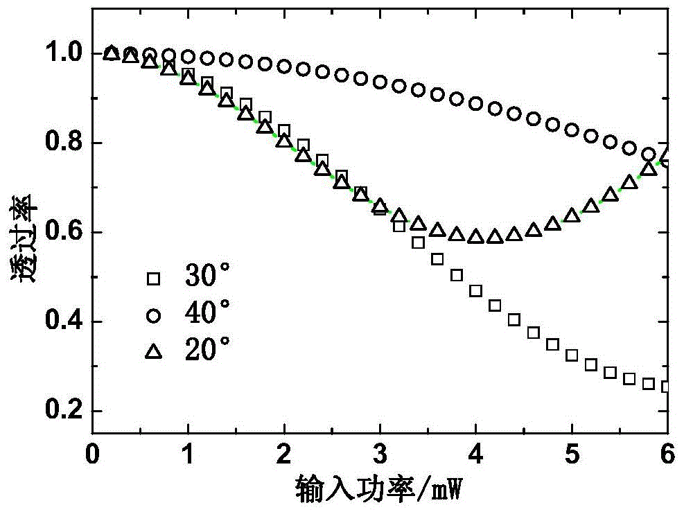
[0028] Wherein, the angle between the long axis direction of the first quarter wave plate 2 and the polarizer 1 is 20-40°, the optical path of the quartz cuvette 4 is 2-5mm, and the wall thickness is 0.5-1mm. The first quarter-wave plate 2 and the second quarter-wave plate 6 are both ach...


PUM


Abstract

The invention discloses an ultrashort pulse optical limiter based on an optical Kerr effect. The ultrashort pulse optical limiter comprises a polarizer, a first quarter-wave plate, a first lens, optical Kerr media, a second lens, a second quarter-wave plate, a polarization analyzer and a diaphragm which are sequentially arranged in the direction of incident light. The first quarter-wave plate and the second quarter-wave plate are orthogonal in the long axis direction, and the polarization detection direction of the polarization analyzer is parallel to the polarization direction of the polarizer. According to the ultrashort pulse optical limiter based on the optical Kerr effect, the polarizer and the first quarter-wave plate are combined to generate elliptically polarized light, the optical Kerr effect generated in the optical Kerr media is further utilized, the polarization ellipse rotation and self-focusing effect are generated through abduction, part of incident light is intercepted when passing through the polarization analyzer and the diaphragm, and accordingly light amplitude limiting output can be achieved. The ultrashort pulse optical limiter based on the optical Kerr effect has the advantages of being high in linear transmissivity, high in response speed, extremely wide in bandwidth, simple in structure and low in cost, thereby being quite suitable for designing and manufacturing ultrashort pulse broadband laser protection devices.

Description

technical field [0001] The invention belongs to the technical field of laser protection, and relates to an ultrashort pulse optical limiter based on the optical Kerr effect. Background technique [0002] As a special light source, laser is playing an increasingly important role in the fields of science and technology, medicine, production and national defense. With the development and improvement of high-power laser technology, lasers have been rapidly developed in modern military affairs, and more laser blinding and laser weapons have appeared on modern battlefields. Facing the threat of new laser weapons, the development of new laser limiting protection devices has become a key scientific and technological problem that needs to be solved urgently in modern science and technology. [0003] Femtosecond laser is an ultra-powerful and ultra-fast laser technology developed rapidly at the end of the 20th century. Unlike other long-pulse lasers and continuous lasers, it has the ...

Claims


Application Information

Patent Timeline
Patent Type & Authority Patents(China)
IPC IPC(8): H01S3/10
Inventor 司金海宋洪磊闫理贺熊耀兵侯洵
Owner XI AN JIAOTONG UNIV
Learn More