Polarized, multicolor LED-based illumination source

a multi-color led and illumination source technology, applied in the field of illumination systems, can solve the problems of compounding the problem of inefficiency in the green portion relatively inefficient leds that operate in the green region of the visible spectrum, etc., and achieve the effect of increasing the angular rang

Inactive Publication Date: 2009-06-02
3M INNOVATIVE PROPERTIES CO
View PDF62 Cites 180 Cited by
  • Summary
  • Abstract
  • Description
  • Claims
  • Application Information

AI Technical Summary

Problems solved by technology

Furthermore, LEDs that operate in the green region of the visible spectrum are known to be relatively inefficient, compared to blue and red LEDs, and so many systems require more green LEDs than blue or red LEDs.
This problem of inefficiency in the green portion of the spectrum is compounded when the light is required to be polarized.

Method used


Image

  • Polarized, multicolor LED-based illumination source
  • Polarized, multicolor LED-based illumination source
  • Polarized, multicolor LED-based illumination source

Examples


Embodiment Construction

[0021]The present invention is applicable to illumination systems, and is more particularly applicable to illumination system for displaying images, for example projection systems such as may be used in projection televisions and displays, monitors and the like.

[0022]It is well known that green light emitting diodes (LEDs) are less efficient than LEDs operating in the blue and red regions of the visible spectrum. Consequently, LED-based illumination systems require more green LEDs than blue and red LEDs to achieve desired levels of brightness and color balance. Instead of generating green light directly with an LED, another approach is to generate light at a first wavelength, for example blue or UV wavelengths, and to convert the light at the first wavelength to a green wavelength.

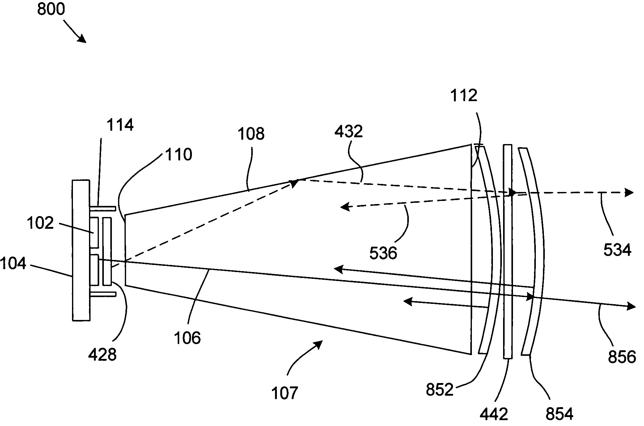
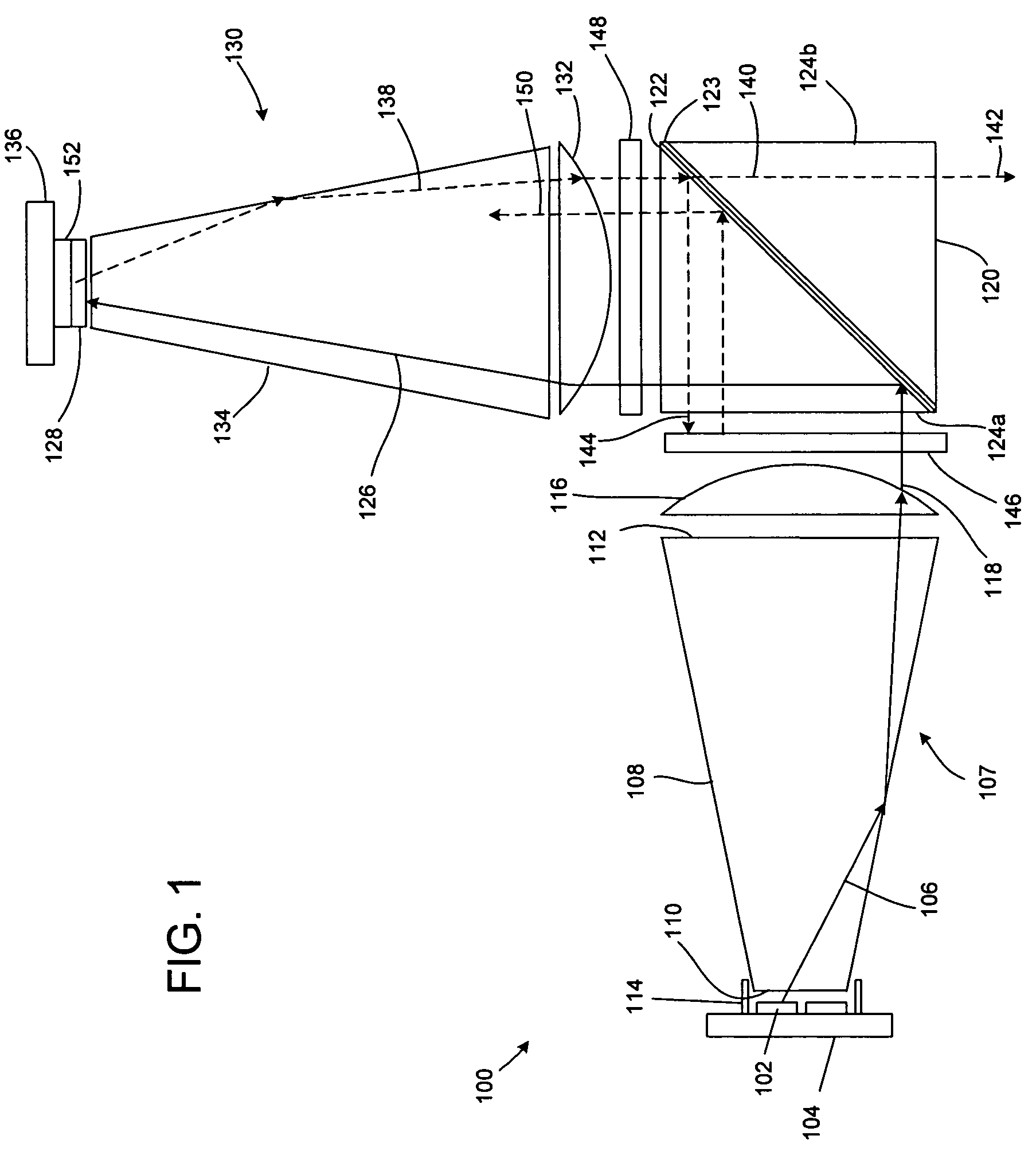
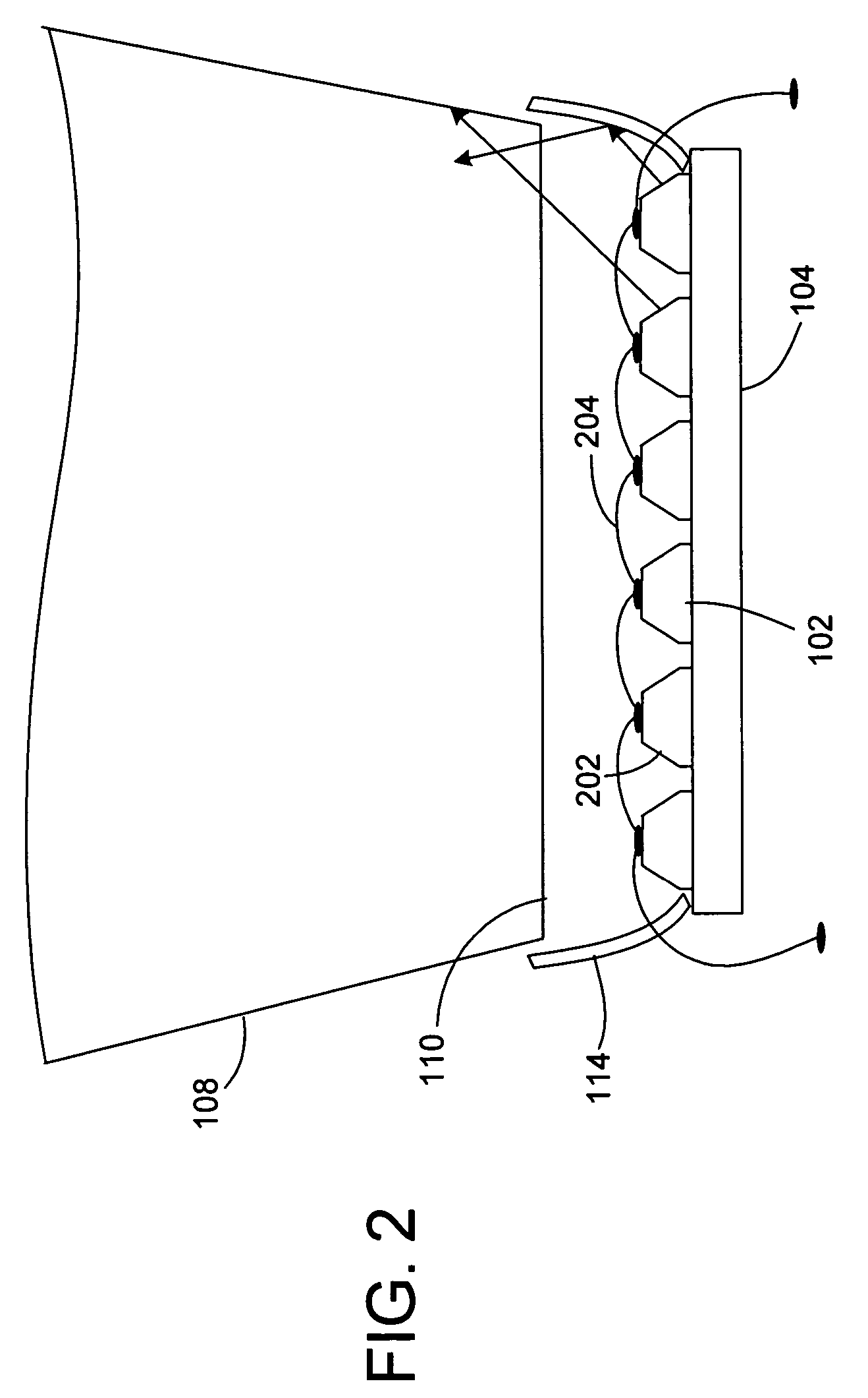
[0023]One exemplary approach that may be useful for wavelength converting light from an LED to generate green light is schematically illustrated in FIG. 1. An exemplary illumination system 100 has an array...


PUM


Abstract

Light emitting diodes (LEDs) emit light at a first wavelength. A phosphor material close to LEDs converts at least some of the light to a second wavelength. The light at both wavelengths passes through a light collecting unit. A reflecting polarizer transmits both wavelengths in a first polarization state and reflects light at both wavelengths in a second, orthogonal, polarization state. Light reflected by the reflective polarizer is directed back towards the phosphor material without any substantial increase in angular range. The resulting output light beam contains polarized light at the first and second wavelengths. In some embodiments, an array of LEDs includes LEDs that emit light at a first wavelength and others that emit light at a second wavelength. The phosphor material is disposed on the LEDs emitting the light at the first wavelength.

Description

FIELD OF THE INVENTION[0001]The present invention relates to illumination systems that may be used in image projection system. More specifically, the invention relates to illumination systems that include an array of light emitting elements, such as light emitting diodes (LEDs) to generate polarized light.BACKGROUND[0002]Illumination systems may be found in many different applications, including image projection display systems, backlights for liquid crystal displays and the like. Projection systems usually use a source of light, illumination optics to pass the light to one or more image-forming devices, projection optics to project the image(s) from the image-forming device(s) and a projection screen on which the image is displayed. The image-forming device(s) are controlled by an electronically conditioned and processed video signal.[0003]White light sources, such as high pressure mercury lamps, have been, and still are, the predominant light sources used in projection display sys...

Claims


Application Information

Patent Timeline
Patent Type & Authority Patents(United States)
IPC IPC(8): G03B21/14F21V7/04G03B21/26G02B1/10G02B27/14H01L33/00H01L33/50H01L33/58H01L33/60
CPCH04N9/3167H04N9/3197G03B21/204G03B21/2073G03B33/06G03B33/12G03B21/20G02B27/18G03B21/28
Inventor CONNER, ARLIE R.
Owner 3M INNOVATIVE PROPERTIES CO
Why Eureka
Try Eureka