Fluorescent Light Fixture Assembly with LED Lighting Element and Converter Modules

a technology of led lighting elements and fluorescent light fixtures, applied in the direction of electric variable regulation, process and machine control, instruments, etc., can solve the problems of high operating voltage, high power consumption, and limitations of conventional fluorescent light fixtures, and achieve the effect of cost-effectiveness

Active Publication Date: 2011-05-26
ELECTRALED
View PDF52 Cites 159 Cited by
  • Summary
  • Abstract
  • Description
  • Claims
  • Application Information

AI Technical Summary

Benefits of technology

[0011]According to one aspect of the invention, the lighting element is installed within a preexisting fluorescent fixture, including the existing ballast. The lighting element receives power from the existing ballast, wherein the converter module provides a constant current source to power the LED array. Thus, the lighting element, including the converter module, can replace the conventional fluorescent light tube, and may be utilized in a cost-effective retrofit manner with the existing ballast.

Problems solved by technology

Conventional fluorescent light fixtures suffer from a number of limitations, including high operating voltages, high power consumption, short life expectancy, and / or poor light output quality in terms of both color temperature and color rendering.
However, the ability to replace fluorescent lamps with LEDs is hindered by operating differences between the two light sources.
These operating differences may require replacement of not only the fluorescent bulb itself, but also some or all of the other components of the fluorescent lighting fixture, resulting in high cost and expenditure of time.
Thus, the power supply circuit 100 taught by the '299 patent suffers from a number of limitations, including but not limited to being costly to manufacture and prone to reliability and operability concerns.

Method used


Image

  • Fluorescent Light Fixture Assembly with LED Lighting Element and Converter Modules
  • Fluorescent Light Fixture Assembly with LED Lighting Element and Converter Modules
  • Fluorescent Light Fixture Assembly with LED Lighting Element and Converter Modules

Examples


Embodiment Construction

[0021]While this invention is susceptible of embodiments in many different forms, there are shown in the drawings and will herein be described in detail preferred embodiments of the invention with the understanding that the present disclosure is to be considered as an exemplification of the principles of the invention and is not intended to limit the broad aspect of the invention to the embodiments illustrated.

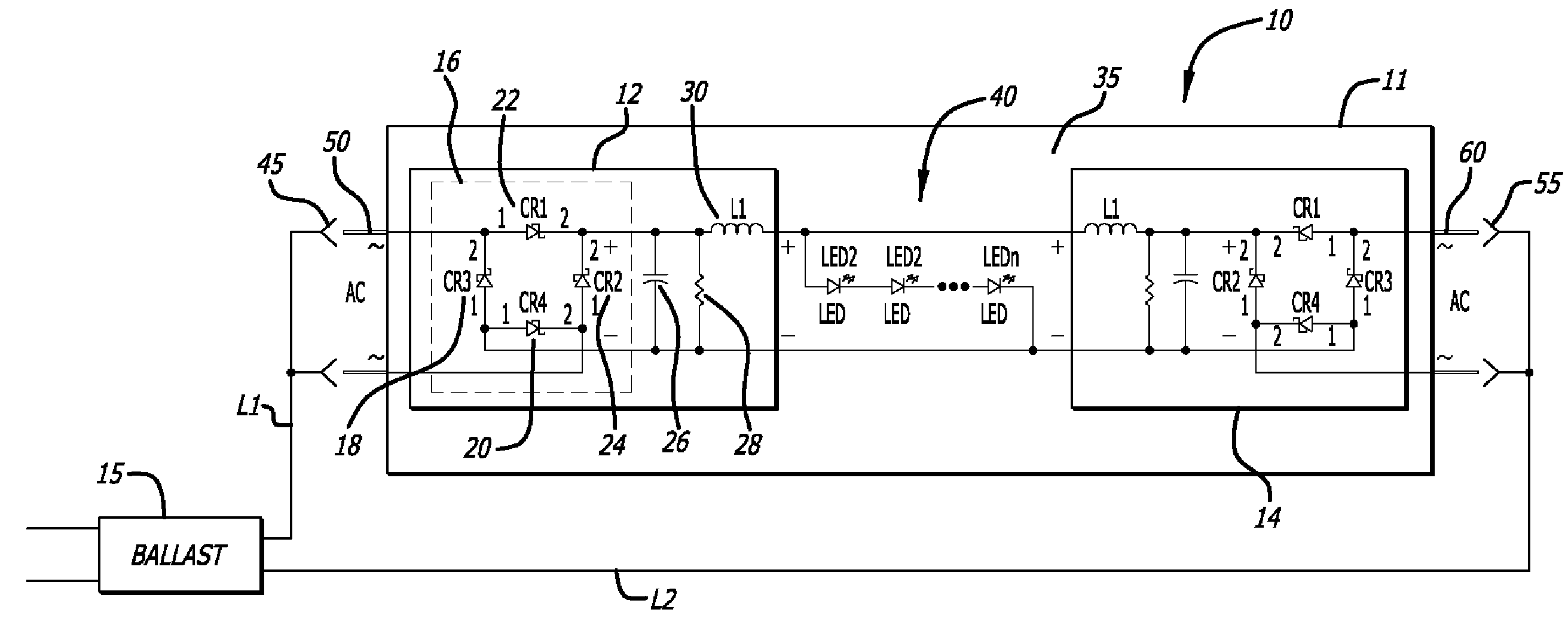
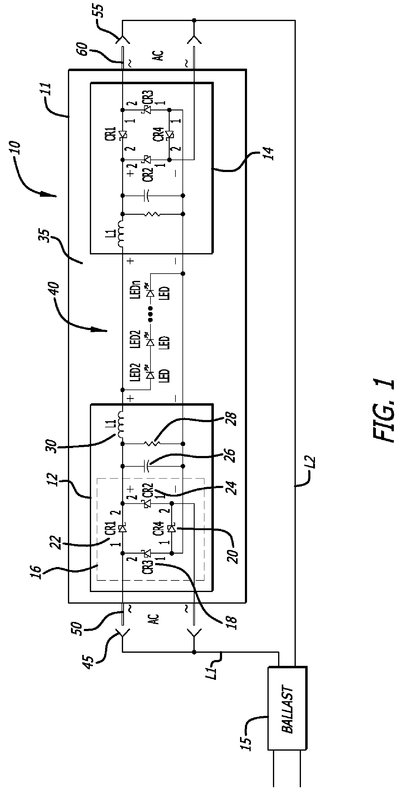
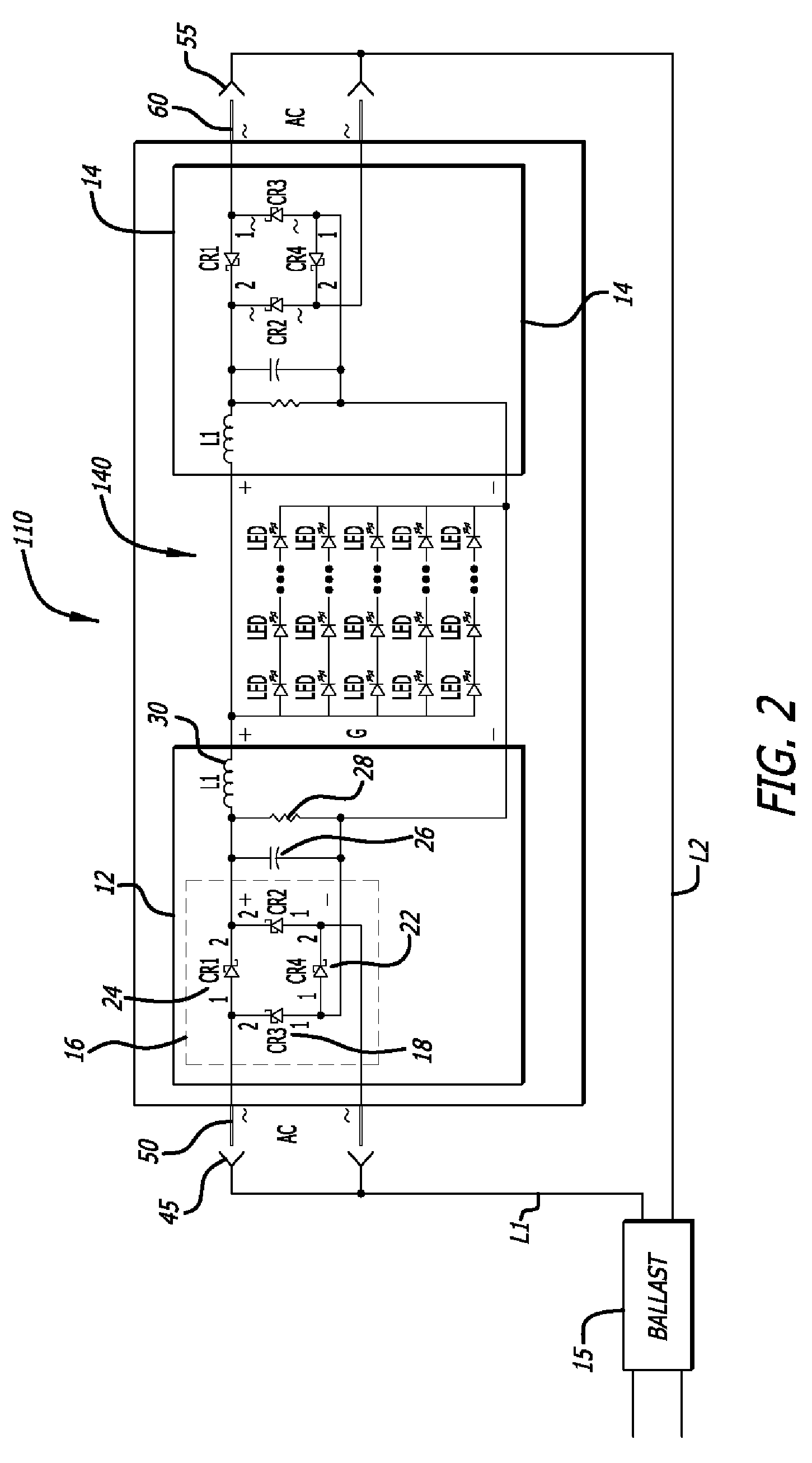
[0022]The present invention is directed to a fluorescent light fixture assembly including a ballast sed to supply power to conventional fluorescent lamps and a novel lighting element 10 that includes an array of LEDs and at least one converter module that enables the existing ballast to supply power to the LED array. The lighting element includes a body configured to fit within a preexisting fluorescent light fixture. In general terms, the lighting element receives power from the pre-existing ballast, wherein the converter module provides a constant current source to power the...


PUM


Abstract

The present invention is directed to a fluorescent light fixture assembly including a ballast and a novel lighting element that includes an array of LEDs and at least one converter module that enables the existing ballast providing an AC power input to supply DC power to the LED array. The lighting element includes a body that contains the LED array and the converter modules and shares the configuration of the lighting element that is to be retrofitted. The lighting element receives power from the pre-existing ballast, wherein the converter module provides a constant current source to power the LED array. Thus, the lighting element, including the converter module, replaces the conventional fluorescent light tube in a cost-effective retrofit manner with the existing ballast.

Description

CROSS-REFERENCE TO RELATED APPLICATIONS[0001]This application claims the benefit of U.S. Provisional Application No. 61 / 281,585 filed Nov. 19, 2009 and U.S. Provisional Application No. 61 / 336,104 filed Jan. 15, 2010.FEDERALLY SPONSORED RESEARCH OR DEVELOPMENT[0002]Not applicable.TECHNICAL FIELD[0003]The invention relates to a fluorescent light fixture assembly including a ballast and a lighting element that includes an array of LEDs and at least one converter module that enables the existing ballast to supply DC power to the LED array.BACKGROUND OF THE INVENTION[0004]Conventional fluorescent light fixtures can be found in a variety of commercial, residential and retail applications. These fixtures typically include a housing, an electronic ballast and at least one fluorescent light tube, which may be linear or curvilinear. The ballast is electrically connected to the power supply, is installed within the fixture housing, and limits the amount of current supplied to the light tube(s)...

Claims


Application Information

Patent Timeline
Patent Type & Authority Applications(United States)
IPC IPC(8): H05B37/02H05B44/00
CPCH05B33/0809Y02B20/342Y02B20/386Y02B20/30H05B45/3725
Inventor THOMAS, JAMESGATESMAN, GARYMOSIER, JAMES
Owner ELECTRALED
Why Eureka
Try Eureka