Transportable lighting device

Inactive Publication Date: 2014-08-07
WACKER NEUSON SE
View PDF2 Cites 40 Cited by
  • Summary
  • Abstract
  • Description
  • Claims
  • Application Information

AI Technical Summary

Benefits of technology

[0032]In a specific embodiment, the holding device can be fashioned below the lower mount of the stand device. In this way, it is possible to provide the holder device, and therewith—when constructed as intended—the ballast as well, at as low a position as possible.
[0033]In a specific embodiment, the holding

Problems solved by technology

In addition to this there is the weight of the housing of the ballast, which has

Method used


Image

  • Transportable lighting device
  • Transportable lighting device
  • Transportable lighting device

Examples


Example

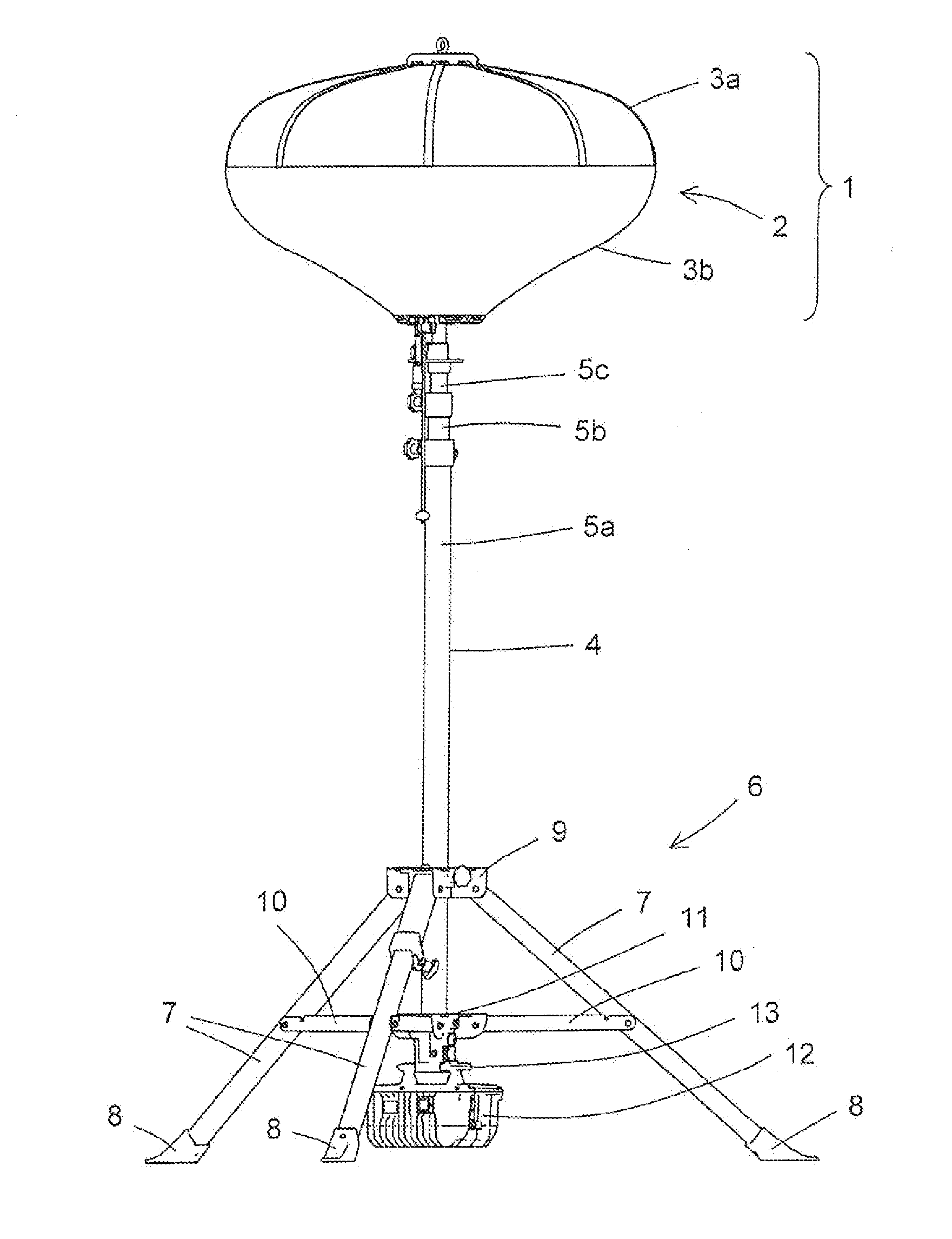
[0039]FIG. 1 shows a transportable lighting device in the operational state.

[0040]The lighting device can be carried comfortably by a user—possibly broken clown into a few components—to the location of use, or to different locations.

[0041]In the upper part of the image, a light apparatus 1 realized as a light balloon is shown. The light apparatus has in its interior a light generator (not shown) that is surrounded almost completely by a light screen 2.

[0042]Light screen 2 is clamped, by clamp (also not shown), in the clamped state shown in FIG. 1, so that it takes on an outer contour resembling an ellipse. Light screen 2 has an upper half 3a made of a reflective fabric, and a lower half 3b made of a material transparent to light.

[0043]The light produced in the interior of light apparatus 1 by the light generator, such as a lamp, thus radiates almost completely downward, and illuminates the work area situated underneath.

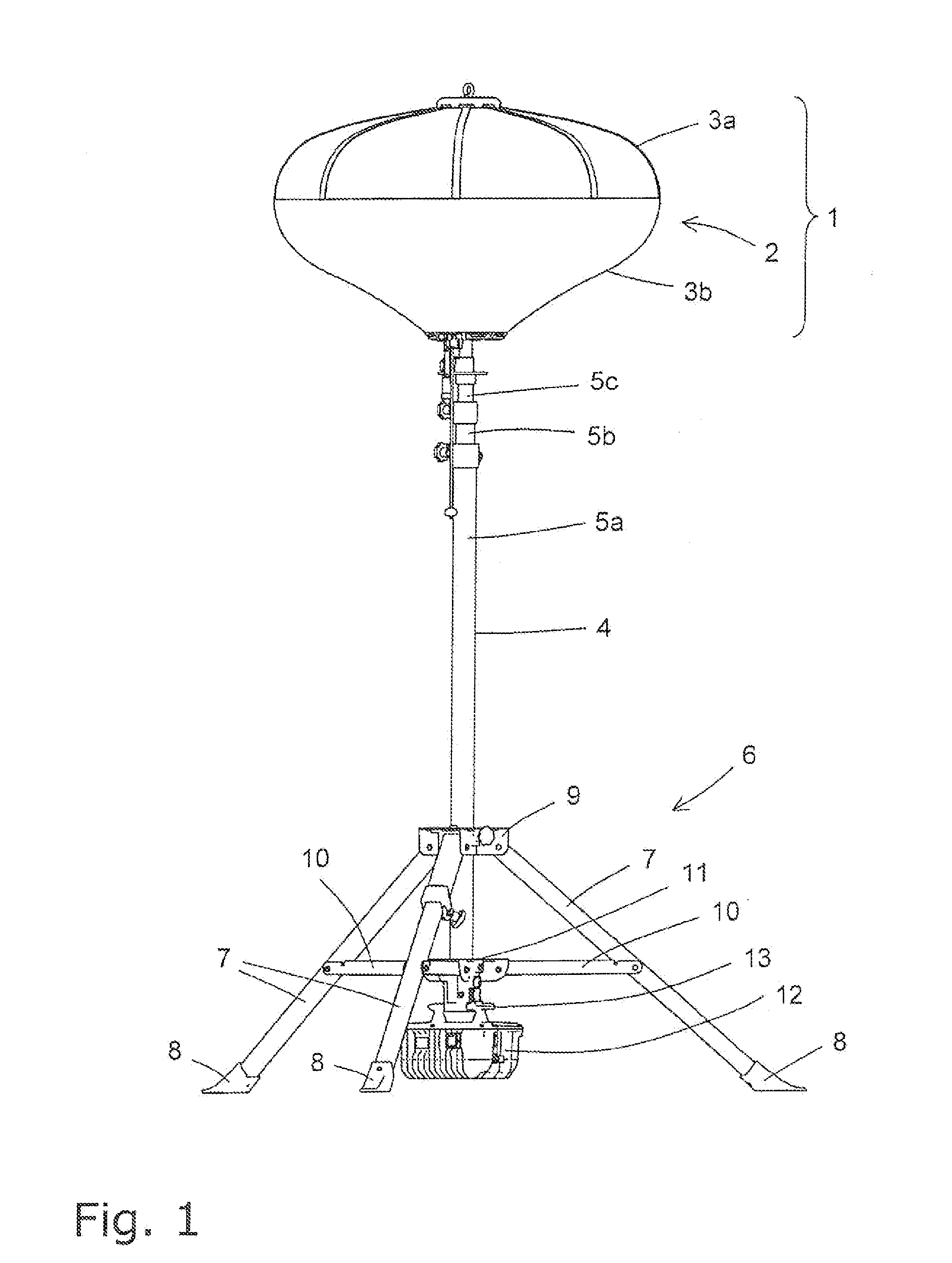
[0044]Light apparatus 1 is borne at its lower side by a column d...


PUM


Abstract

A transportable lighting device has a light apparatus, a column device that bears the light apparatus and that extends in a longitudinal direction, and a stand device that bears the column device. In order to provide electrical power for the light apparatus, a ballast is provided that is situated on the column device, underneath the column device in the longitudinal direction. In this way, the overall center of gravity of the transportable lighting device can be shifted significantly downward, This results in improved stability against falling.

Description

BACKGROUND OF THE INVENTION[0001]1. Field of the Invention[0002]The present invention relates to a transportable lighting device.[0003]2. Description of the Related Art[0004]Transportable lighting devices are known, as stand lights, and are used for example for temporary illumination of a construction site an accident site, or a work site[0005]EP 1 059 483 A2 indicates such a transportable lighting device. The lighting device is made up essentially of a light balloon having a light source, for example a metal vapor halogen lamp (also known as a metal-halide lamp), and a stand having an extendable telescope with the aid of which the height of the light balloon having the light source can be adjusted. In this way, it is possible to extend the telescope far enough that the light source reaches a height of 4 to 5 m, in order to achieve a uniform illumination of the work site.[0006]In addition, a ballast is standardly provided that is required in order to provide electric power, and thus...

Claims


Application Information

Patent Timeline
IPC IPC(8): F21V23/02F21L14/00F21V11/00F21V17/04F21V21/22
CPCF21V23/026F21L14/00F21V21/22F21V17/04F21V11/00F21V21/06F21W2131/1005
Inventor MAHLING, EVAHARTKOPF, CHRISTIAN
Owner WACKER NEUSON SE
Why Eureka
Try Eureka