Toilet bowl

A toilet, flushing water technology, applied in flushing toilets, urinals, water supply devices, etc., can solve the problems of unavoidable excessive water spray, strong whirlpools, and increased production costs of toilet seats.

Active Publication Date: 2013-06-05
吉博力凯乐米服务公司
View PDF8 Cites 8 Cited by
  • Summary
  • Abstract
  • Description
  • Claims
  • Application Information

AI Technical Summary

Problems solved by technology

[0003] A particular problem is, for example, the use of toilet seats in the case of retrofitting with different flush tanks which themselves have different flush water flows
Therefore, the production cost of the toilet seat increases
[0004] Another problem with toilet seats w...

Method used


Image

  • Toilet bowl
  • Toilet bowl
  • Toilet bowl

Examples


Embodiment Construction

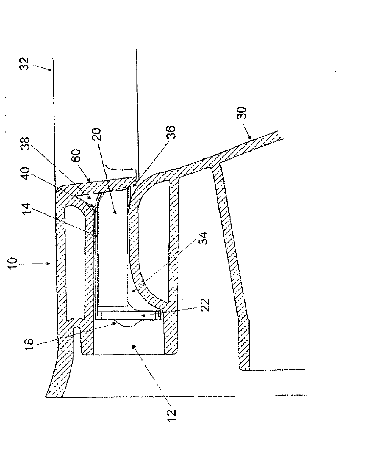
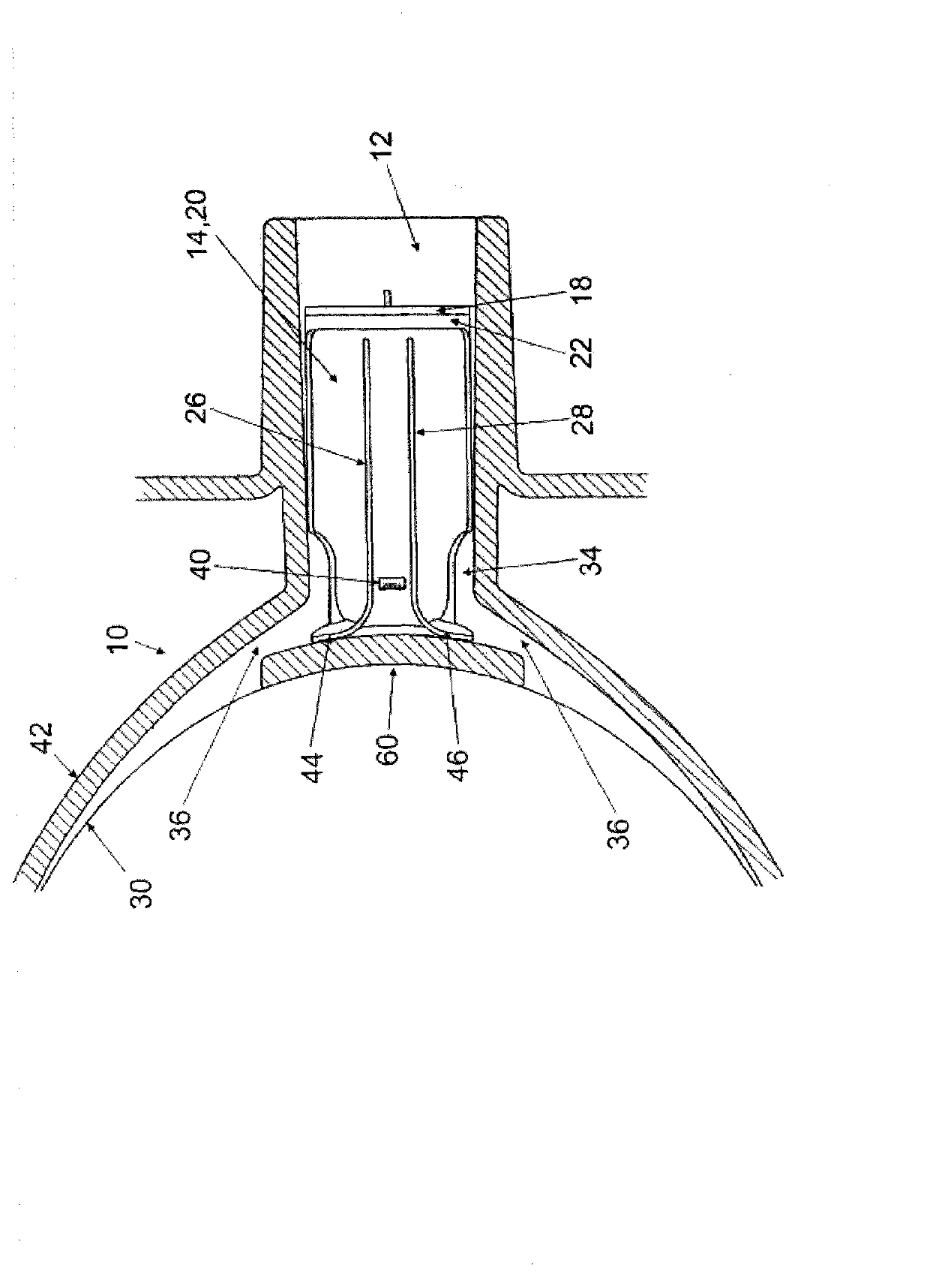
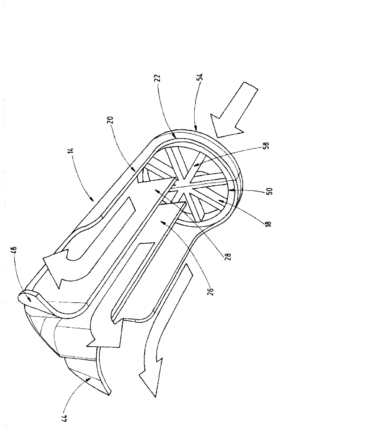
[0029] figure 1 and 2 Shown are schematic partial cross-sectional views of a toilet seat 10 with a flush water distributor 14 and a flush water flow restriction 18 according to the invention. figure 1 The cut plane in the extends vertically, while figure 2 The cut plane extends horizontally. The toilet seat 10 has an inner wall surface 30 and an outer wall surface 42 . The flushing water flows through the flushing water inlet 12 into the flushing water distributor 14 and is divided there into three different channels. These channels are formed by the shell surface of the main body 20 , the first inner wall 26 and the second inner wall 28 . especially if figure 2 As shown, the inner walls 26 , 28 have curved regions 44 and 46 in the region facing the inner wall surface 30 , which deflect the flushing water towards the lateral outflow opening 36 . The flushing water in the intermediate channel between the inner walls 26, 28 passes through another especially in the figur...


PUM


Abstract

The present invention relates to a toilet bowl, and in particular the present invention relates to a toilet bowl without a flushing rim. According to the invention, a toilet bowl (10) with a flushing water distributor (14) is disclosed, wherein the flushing water distributor (14) is arranged in the region of a flushing water inlet (12) and has fixing means (24) for the releasable locking of a flushing flow throttle (18).

Description

technical field [0001] The invention relates to a toilet seat, in particular to a toilet seat without a flushing retainer. Background technique [0002] The toilet seat can be flushed by a flush tank or a pressure flush system. In any case, according to European Standard E-N997 various requirements are placed on flushing toilet seats. In addition, it must be ensured that the inner wall is flushed and that overflow of the spray water (overspray) is avoided. These requirements lead to increased precision requirements for certain parts such as the flush water distributor, especially for toilet seats without flush rims. [0003] A particular problem is, for example, the use of the toilet seat when retrofitted with a different flush tank which itself has a different flush water flow. Therefore, the flushing water flow of the old-fashioned flushing tank is generally in the range of 3 liters / second, and the flushing water flow of the new-style flushing water tank is 2 liters / sec...

Claims


Application Information

Patent Timeline
IPC IPC(8): E03D11/13
CPCE03D11/13E03D11/08E03D2201/40
Inventor 丹尼斯·施罗卡
Owner 吉博力凯乐米服务公司
Why Eureka
Try Eureka