Internal combustion engine

a crankcase and internal combustion technology, applied in the direction of engine lubrication, non-fuel substance addition to fuel, air cleaner for fuel, etc., can solve the problems of high casting complexity, high power output required, and high space requirement, so as to increase the oil flow, the effect of increasing the oil flow

Active Publication Date: 2009-01-06
DR ING H C F PORSCHE AG
View PDF12 Cites 7 Cited by
  • Summary
  • Abstract
  • Description
  • Claims
  • Application Information

AI Technical Summary

Benefits of technology

[0007]The result of the present invention's integral configuration of at least one air / oil separator with the oil scrapers is a very compact type of construction of these two parts, so that they may be integrated into the internal combustion engine without any problems. In addition, the negligible spacing between the air / oil separator and the oil scrapers eliminates the need for a pump, since the oil is scraped off due to the high kinetic energies prevailing in the air / oil separator. Furthermore, to the density difference between air and oil allows the oil to be separated automatically, such an automatic oil separation being the goal. Another advantage of the present invention lies in the feature that no additional channels or the like have to be integrated into the crankcase, thus eliminating any additional casting complexity.
[0008]In each driving state of the motor vehicle provided with the internal combustion engine of the invention, at least one oil outlet opening of the air / oil separator is located above the oil level in the oil pan. Thus, the oil is always guaranteed to return to the oil pan without any constraints and without resistance. Preferably all of the oil outlet openings are arranged above the oil level occurring in the oil pan.
[0009]If in an advantageous further embodiment of the invention the longitudinal axis of the air / oil separator, around which the oil that is introduced rotates, runs substantially parallel to the crankshaft, then additional space problems are eliminated, because the air / oil separator is usually much larger in the direction of its longitudinal axis than in a plane perpendicular thereto. That is, the air / oil separator is installed in a reclining manner. Yet this feature does not have a negative impact on its function, because the oil does not flow into said air / oil separator due to gravity, but rather due to high centrifugal force.
[0010]An especially large amount of oil may be scraped from the crankshaft rotating in the crankcase if each oil scraper is assigned to a connecting rod and each oil scraper has two oil scraping openings arranged one after the other in succession in the crankshaft rotation direction.
[0011]Furthermore, a tapering channel may be provided to run from each oil scraping opening to the air / oil separator. Such a tapering channel can increase the oil flow, rate and the oil may thus be guided even faster to the air / oil separator.

Problems solved by technology

However, the drawback with this feature is high casting complexity in producing the relatively long channels, the high space requirement, and the high power output required to circulate the oil and to separate the air from the oil.
Yet this prior art design does not make it possible to separate the air from the oil returned to the oil pan.

Method used


Image

  • Internal combustion engine
  • Internal combustion engine
  • Internal combustion engine

Examples


Embodiment Construction

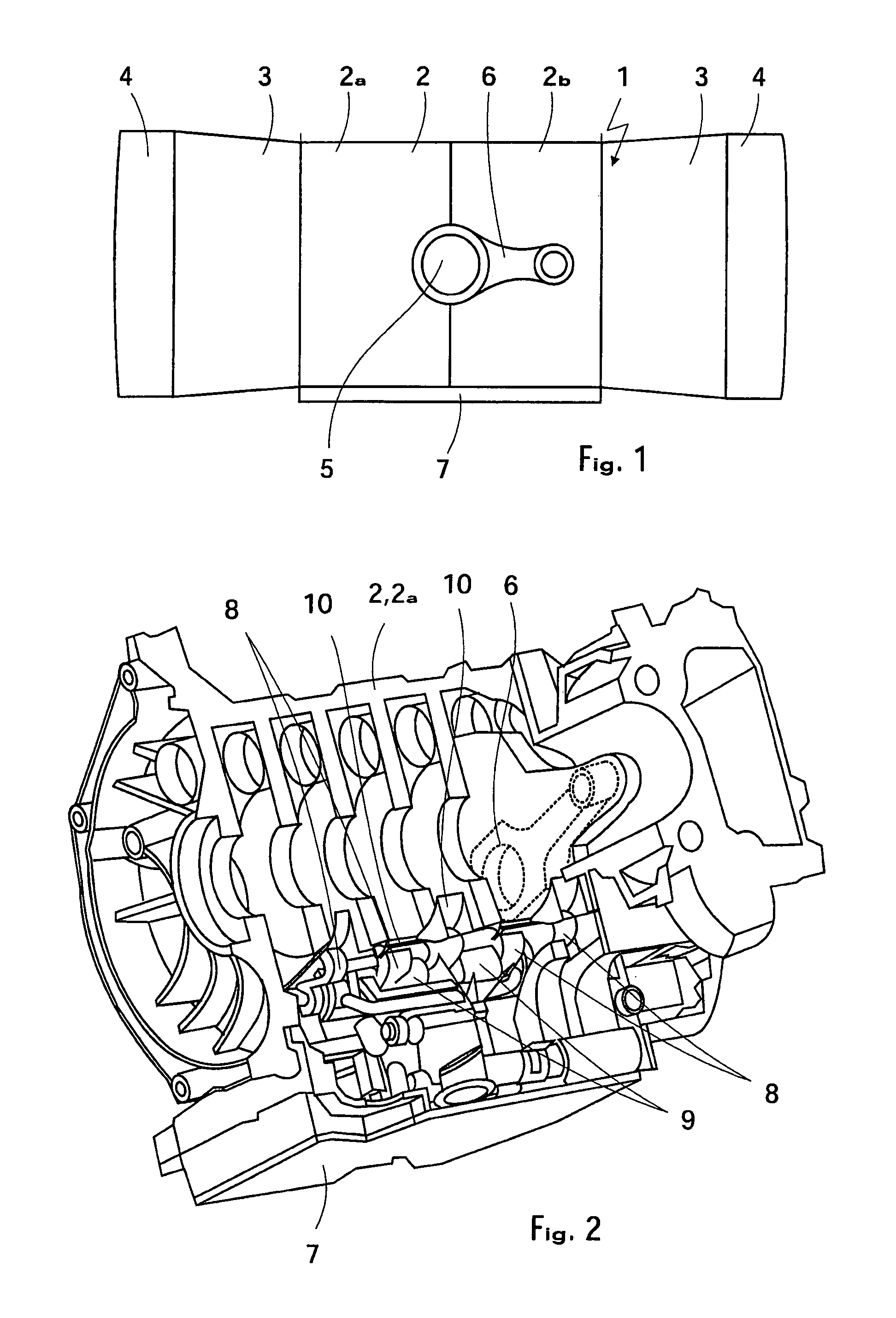
[0020]FIG. 1 depicts an internal combustion engine 1 with a crankcase 2, cylinder heads 3 mounted on the crankcase 2; and cylinder head covers 4 closing the cylinder heads 3 in a conventional manner. In this case the internal combustion engine 1 is a Boxer configuration, but it could also be configured according to any other known construction.

[0021]In the present invention, the crankcase 2 has two crankcase halves 2a, 2b, between which is mounted a crankshaft 5 with a plurality of attached connecting rods 6. The crankshaft performs a known rotational motion. For the sake of simplicity, only one of the connecting rods 6 is shown. However, the number of connecting rods matches the number of cylinders (not illustrated) of the internal combustion engine 1 and can, therefore, vary almost arbitrarily. Below the crankcase 2 there is an oil pan 7 which holds the oil that is used to lubricate the internal combustion engine 1. Therefore, the internal combustion engine 1 has a wet sump lubric...


PUM


Abstract

An internal combustion engine includes a crankcase in which a crankshaft is rotatably mounted. Mechanisms are provided for scraping off the oil from the rotating crankshaft. An oil pan is arranged below the crankcase for holding the oil scraped off by the scrapers.

Description

RELATED APPLICATIONS[0001]This application claims the benefit of priority under 35 U.S.C. § 119 to German patent application no. 10 2006 035 888.0, filed Jul. 31, 2006, the disclosure of which is incorporated by reference herein.BACKGROUND AND SUMMARY OF THE INVENTION[0002]The present invention relates to an internal combustion engine with a crankcase, in which a crankshaft is mounted in a rotatable manner.[0003]An internal combustion engine is disclosed in DE 44 24 248 C1. The oil is pumped over pressurized channels, running inside the walls of the cylinder head, and the adjoining longitudinal channels to air / oil separating elements inside the crankcase, in order to separate the air from the oil, flowing back into the oil pan. This separation of the air from the oil maintains the quality of the oil and guarantees that the internal combustion engine will operate reliably. However, the drawback with this feature is high casting complexity in producing the relatively long channels, th...

Claims


Application Information

Patent Timeline
Patent Type & Authority Patents(United States)
IPC IPC(8): F01M11/00
CPCF01M11/0004F01M13/00F01M2011/0033F01M2011/005
Inventor REUSTLE, ALBRECHT
Owner DR ING H C F PORSCHE AG
Why Eureka
Try Eureka