Apparatus and method for conveying objects transversely

a transverse and object technology, applied in the direction of mechanical conveyors, conveyor parts, thin material processing, etc., can solve the problems of short displacement path, inability to produce large-scale production, and inability to control the flow of reams, etc., to achieve simple and compact distribution and flexible distribution

Active Publication Date: 2007-05-29
BW PAPERSYSTEMS HAMBURG GMBH
View PDF17 Cites 7 Cited by
  • Summary
  • Abstract
  • Description
  • Claims
  • Application Information

AI Technical Summary

Benefits of technology

[0008]The present invention provides a simple and compact apparatus which ensures more flexible distribution of the reams supplied, to the subsequent packing machines.
[0010]Advantageously, the sliding element can be driven actively and the equalizing element can be moved passively. As a result, only one drive is required. By driving the sliding element it is possible to change the transport region, namely, lengthen or shorten it, at the same time shortening or lengthening the return region, whereby equalisation takes place automatically, retaining the tension of the conveying elements.
[0012]A particularly preferred apparatus provides that the sliding element or sliding carriage includes, in each case, only one tensioning or guiding roller of each set of deflecting rollers. As a result, a particularly compact construction of the apparatus can be achieved. This, at the same time, leads to an increase in the path of displacement of the sliding element.
[0013]Preferably, a common tensioning device is provided for both conveying elements, with the result that firstly costs are saved and secondly a compact design of the apparatus is produced.
[0014]Advantageously, each transport region is assigned a supporting device which for its part is in each case variable in length in the direction of transport of the sliding element. Thus support of the transport regions is obtained, so that, particularly when the transport regions are subjected to a load in the form of stacks of reams or acted upon by operators, sagging of the transport regions is effectively prevented.

Problems solved by technology

A drawback of the known apparatus, however, is that, due to the dimension of the sliding element which is used to receive guiding or tensioning rollers, on the one hand, and equalizing rollers, on the other hand, only a short path of displacement can be produced.
The division of the stream of reams is therefore very limited.
However, as the capacity of the packing machines is limited, and so the production machines produces more reams than can be accepted by a packing machine, the throughput of the production machine must inevitably be throttled, which in turn leads to production losses.

Method used


Image

  • Apparatus and method for conveying objects transversely
  • Apparatus and method for conveying objects transversely
  • Apparatus and method for conveying objects transversely

Examples


Embodiment Construction

[0044]The particulars shown herein are by way of example and for purposes of illustrative discussion of the embodiments of the present invention only and are presented in the cause of providing what is believed to be the most useful and readily understood description of the principles and conceptual aspects of the present invention. In this regard, no attempt is made to show structural details of the present invention in more detail than is necessary for the fundamental understanding of the present invention, the description is taken with the drawings making apparent to those skilled in the art how the forms of the present invention may be embodied in practice.

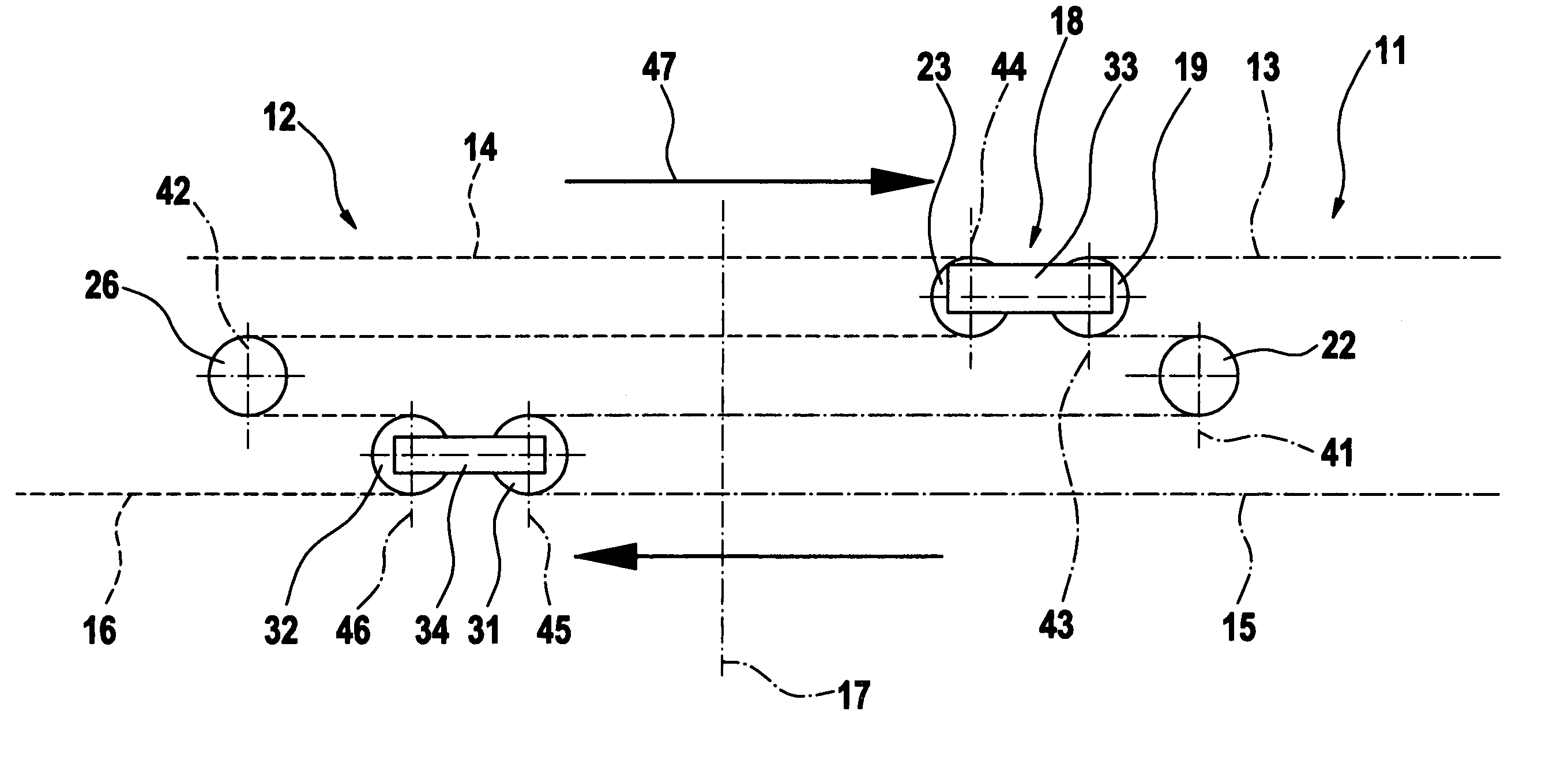
[0045]By way of non-limiting example, the invention concerns an apparatus for the transport of reams of paper transversely to their direction of initial transport from a production machine.

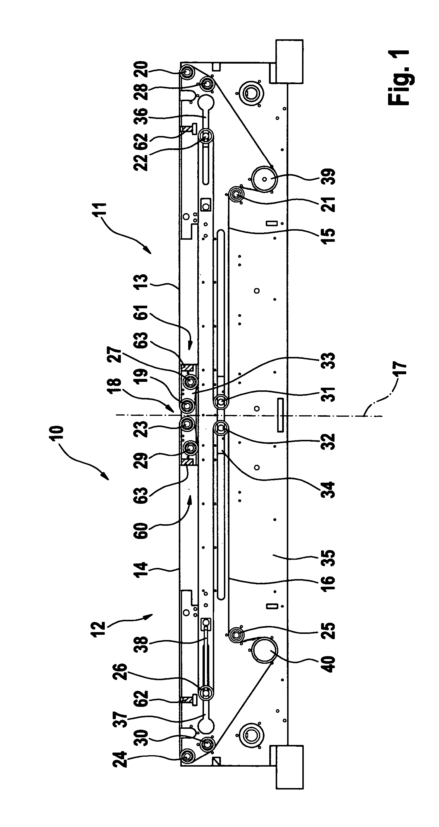
[0046]FIG. 1 shows an apparatus 10 for conveying layers of sheets or stacks of sheets, so-called reams, transversely to their direction of ...


PUM


Abstract

Apparatus and method for conveying objects generally transversely to a direction of initial delivery. The apparatus uses two conveying arrangements which can move independently of one another. Each of the two conveying arrangements have a transport region and a return region. A dividing gap is arranged between the two conveying arrangements. A sliding mechanism can be positioned to at least one of adjust a length of the transport regions and adjust a length of the return regions. An equalizing mechanism can be positioned to at least one of compensate for the change in the return regions and compensate for the change in the transport regions. The sliding mechanism and the equalizing mechanism are separate mechanisms. This Abstract is not intended to define the invention disclosed in the specification, nor intended to limit the scope of the invention in any way.

Description

CROSS-REFERENCE TO RELATED APPLICATIONS[0001]The present application claims priority under 35 U.S.C. § 119 of European Patent Application No. 03090247.2, filed on Aug. 1, 2003, the disclosure of which is expressly incorporated by reference herein in its entirety.BACKGROUND OF THE INVENTION[0002]1. Field of the Invention[0003]The invention concerns an apparatus for conveying objects transversely to their direction of initial transport. The device essentially includes two conveying elements which each have a transport region and a return region and which can be driven independently of each other by way of a drive. These elements are located opposite each other and form a dividing gap with an imaginary center axis. In each case, a set of deflecting rollers for guiding, tensioning and equalizing the conveying elements is utilized. A sliding element for changing the transport region or return region is provided. The sliding element connects the conveying elements to each other. An equali...

Claims


Application Information

Patent Timeline
Patent Type & Authority Patents(United States)
IPC IPC(8): B65G21/14B65G15/06B65G47/26B65G47/68B65H29/16
CPCB65G21/14B65G47/26
Inventor VOIGTLANDER, VOLKMAR
Owner BW PAPERSYSTEMS HAMBURG GMBH
Why Eureka
Try Eureka