Multi-mode filter
- Summary
- Abstract
- Description
- Claims
- Application Information
AI Technical Summary
Benefits of technology
Problems solved by technology
Method used
Image
Examples
Embodiment Construction
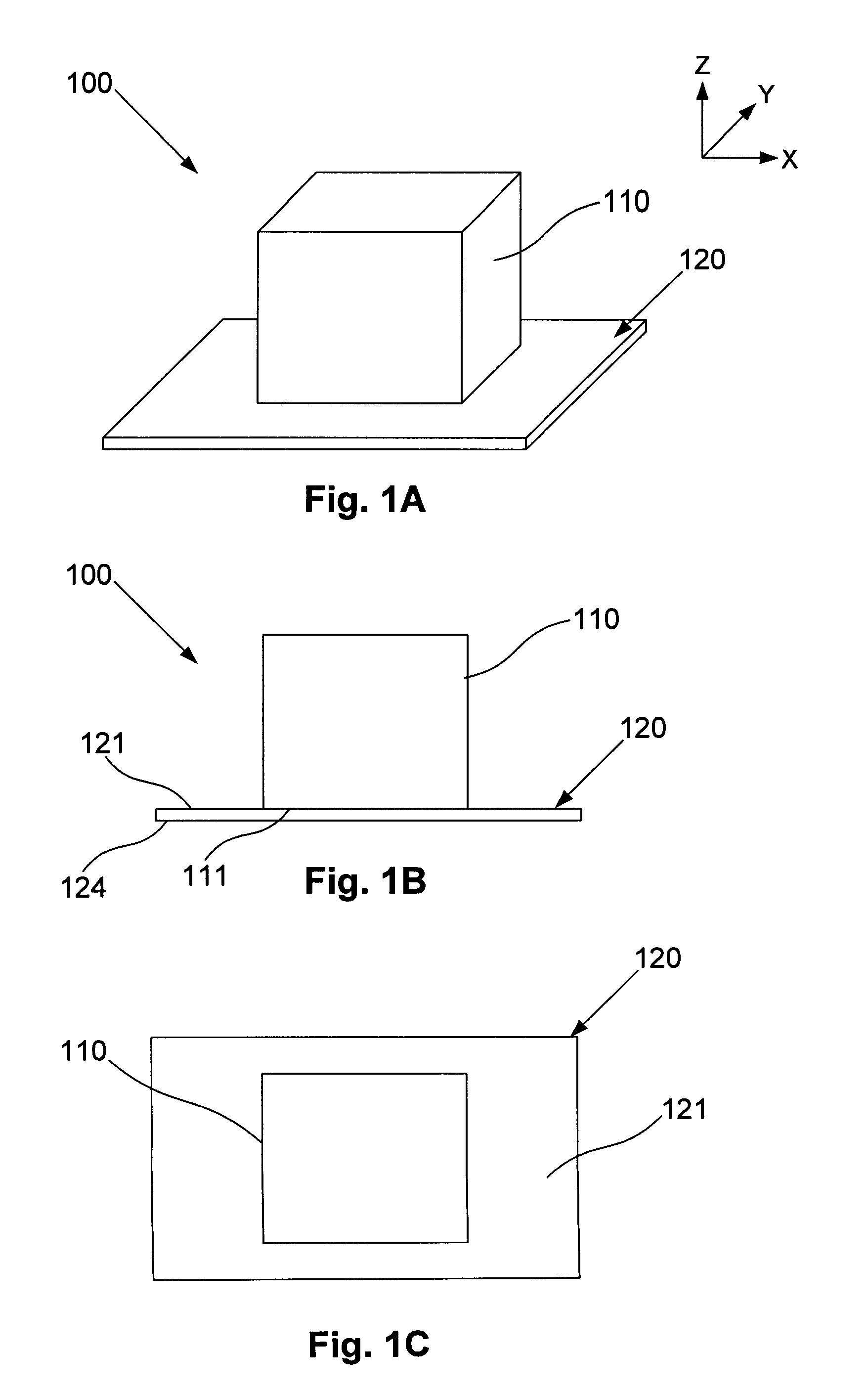
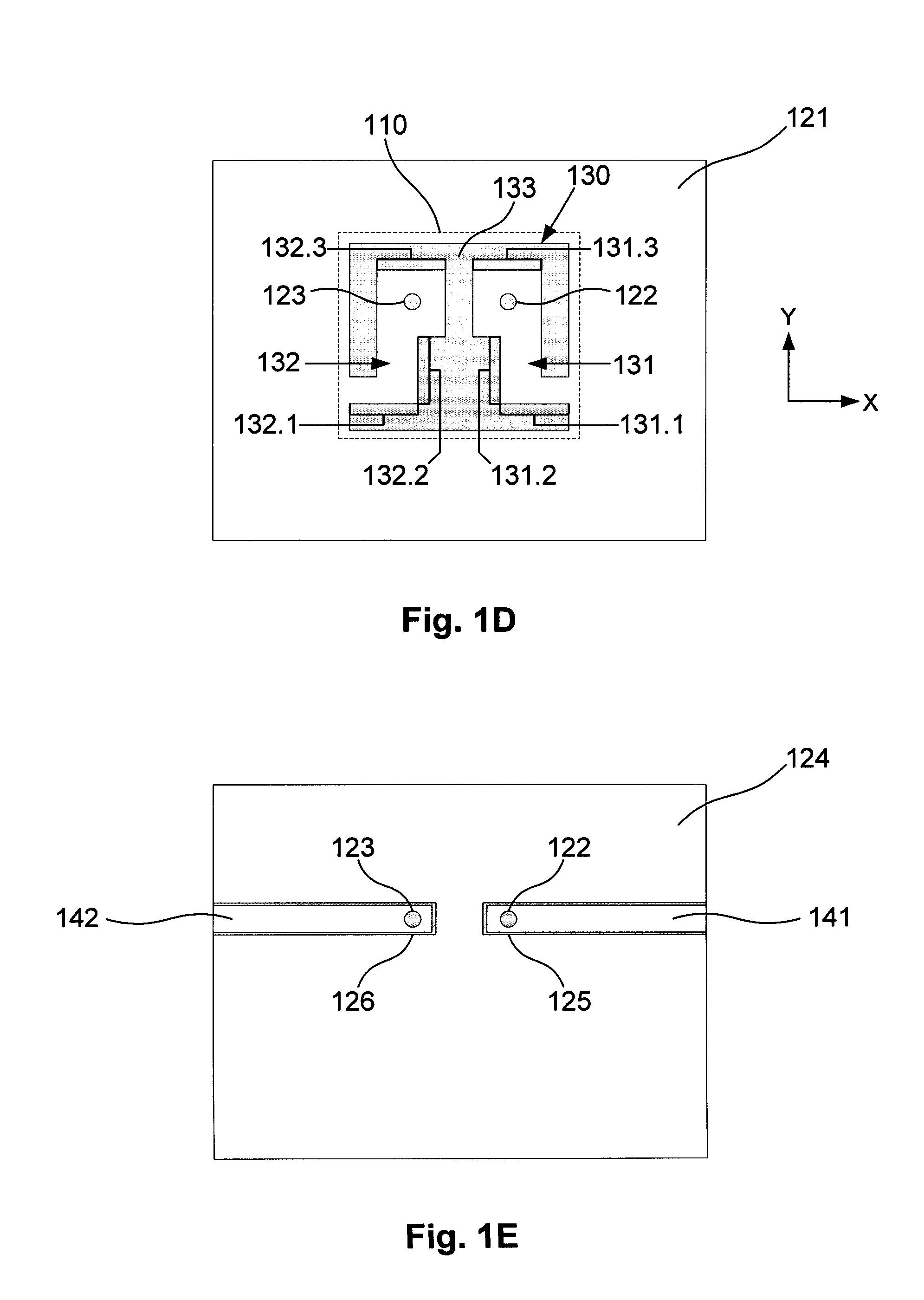
[0128]An example of a multi-mode filter will now be described with reference to FIGS. 1A to 1E.
[0129]In this example, the filter 100 includes a resonator body 110, and a coupling structure 130. The coupling structure 130 at least one coupling 131, 132, which includes an electrically conductive coupling path extending adjacent at least part of a surface 111 of the resonator body 110, so that the coupling structure 130 provides coupling to a plurality of the resonance modes of the resonator body.
[0130]In use, a radio frequency signal, containing, say, frequencies from within the 1 MHz to 100 GHz range, can be supplied to or received from the at least one coupling 131, 132. In a suitable configuration, this allows a signal to be filtered to be supplied to the resonator body 110 for filtering, or can allow a filtered signal to be obtained from the resonator body, as will be described in more detail below.
[0131]The use of electrically conductive coupling paths 131, 132 extending adjacent...
PUM
| Property | Measurement | Unit |
|---|---|---|
| Electrical conductor | aaaaa | aaaaa |
Abstract
Description
Claims
Application Information
 - R&D
- Intellectual Property
- Life Sciences
- Materials
- Tech Scout
- Unparalleled Data Quality
- Higher Quality Content
- 60% Fewer Hallucinations
Browse by: Latest US Patents, China's latest patents, Technical Efficacy Thesaurus, Application Domain, Technology Topic, Popular Technical Reports.
© 2025 PatSnap. All rights reserved.Legal|Privacy policy|Modern Slavery Act Transparency Statement|Sitemap|About US| Contact US: help@patsnap.com


