Endoscope with integrated light source

an endoscope and light source technology, applied in exposure control, printing, instruments, etc., can solve the problems of extremely bright light, extremely inefficient system, hazardous conditions,

Active Publication Date: 2006-08-03
STRYKER CORP
View PDF18 Cites 162 Cited by
  • Summary
  • Abstract
  • Description
  • Claims
  • Application Information

AI Technical Summary

Problems solved by technology

This system is extremely inefficient and must generate extremely bright light to compensate for the distance the light rays must travel and the losses experienced through the system.
This system may also cause infrared heat energy to be transmitted into the patient, which can create hazardous conditions during the surgery.
Furthermore, the color content of the light cannot be controlled, which can adversely affect image quality, and the light cable that connects the light source to the scope is cumbersome.
There are, however, at least two problems with this kind of design.
First, the space inside the tip or annular area of the scope shaft is relatively small.
Therefore, very few LEDs can be integrated into the endoscope.
Second, because endoscopes can come in different sizes, an LED based light source must be specifically designed for a particular endoscope size if it is placed in the tip or annular area of the scope shaft.
It is difficult to obtain the light output required for endoscopic applications in a compact space, as the packaging is often on the order of 50× the size of the LED.
If multiple LEDs are placed on one circuit board, their proximity becomes limited by required heat dissipation.
In addition, at a surgical site within a patient's body, some anatomical surfaces may be closer to the endoscope tip, where light is emitted, than other surfaces; as such, some portions of the image may become overly bright or overly dark.

Method used


Image

  • Endoscope with integrated light source
  • Endoscope with integrated light source
  • Endoscope with integrated light source

Examples


Embodiment Construction

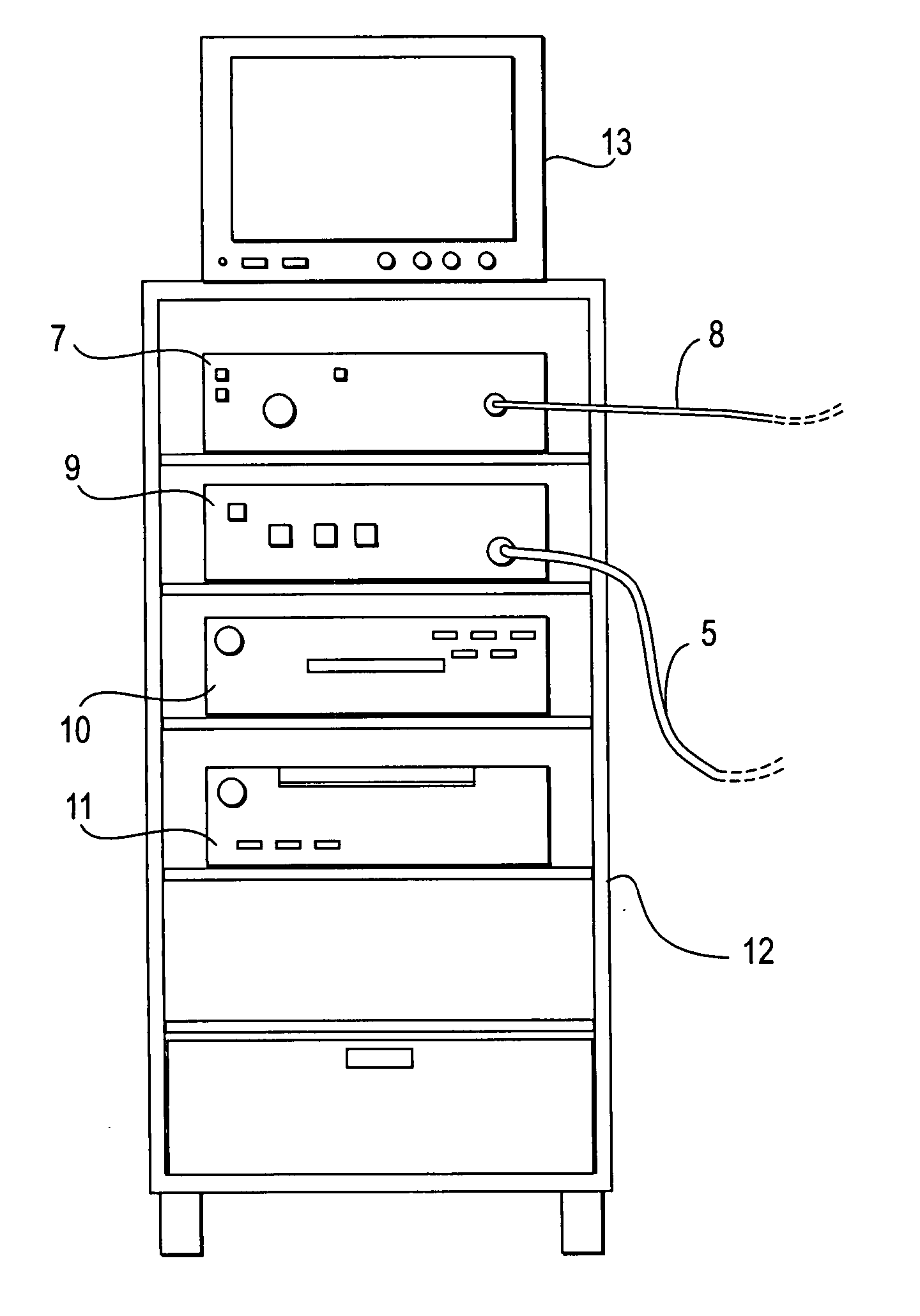
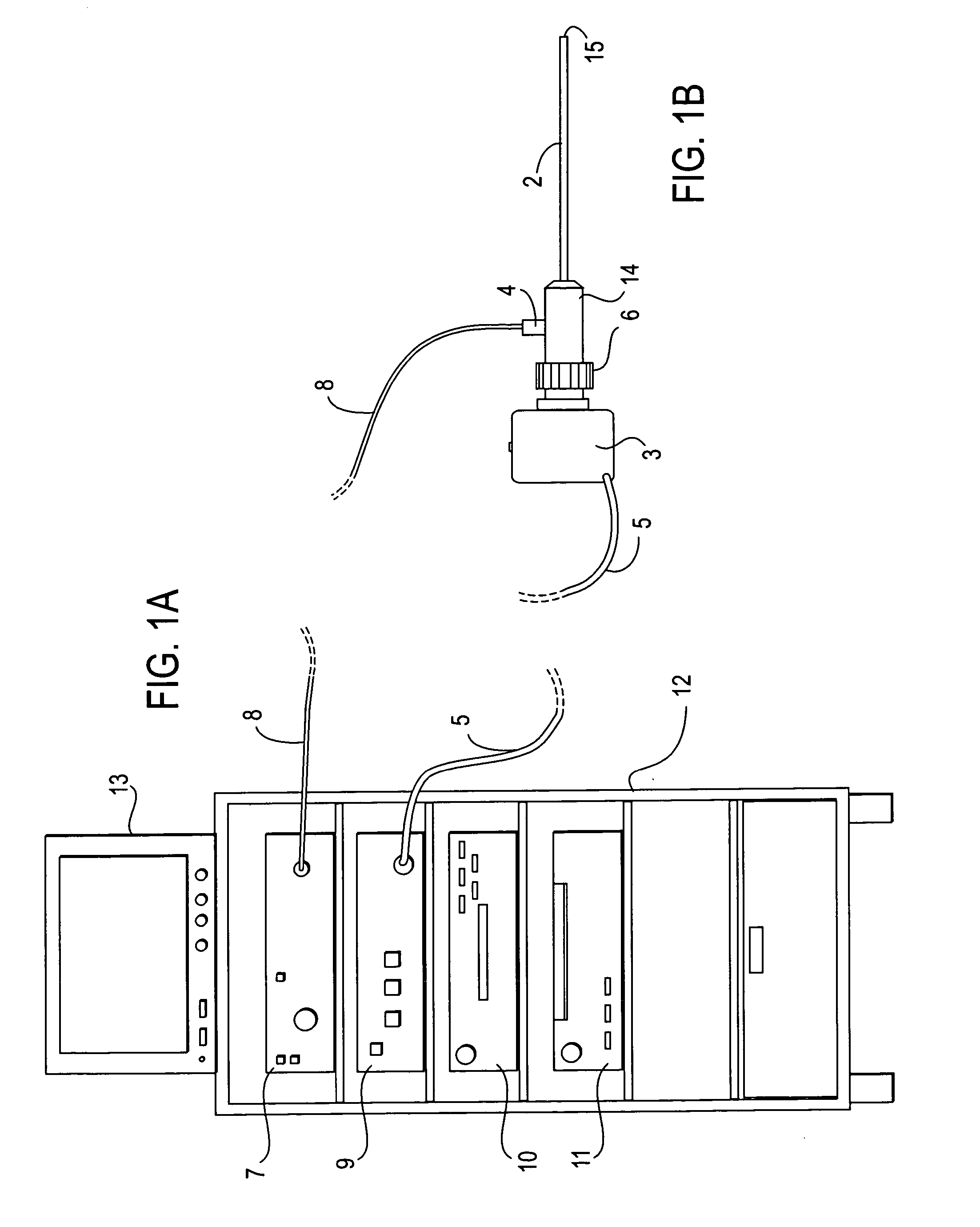
[0033] An LED light source unit for an endoscopic imaging system is described. Note that in this description, references to “one embodiment” or “an embodiment” mean that the feature being referred to is included in at least one embodiment of the present invention. Further, separate references to “one embodiment” in this description do not necessarily refer to the same embodiment. Thus, the present invention can include any variety of combinations and / or integrations of the embodiments described herein.

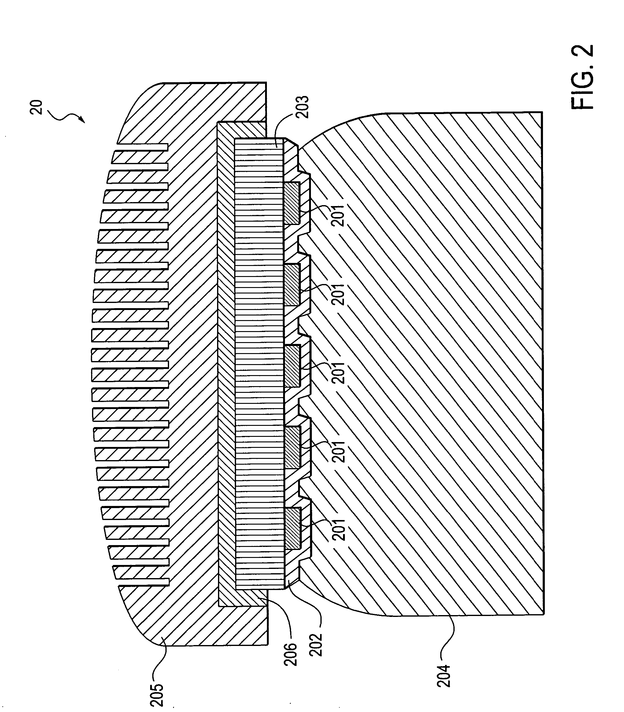
[0034] As described in greater detail below, an LED based light source unit may include an array of LEDs mounted to a thermally conductive substrate, to increase the number of LEDs used while reducing the overall size of the light source unit, and while allowing for sufficient heat dissipation. To further improve heat dissipation, the substrate is mounted to a heat sink or heat pipe.

[0035] Although the embodiments described herein are based on the use of LEDs, it may be possible to r...


PUM


Abstract

An LED based light source unit for an endoscopic imaging system produces illumination for a camera through an endoscope. The light source unit includes an array of LEDs mounted to a thermally conductive substrate. The light source unit is integrated into the proximal end of an endoscope and coupled directly to the optical fibers running to the tip of the endoscope. A plurality of such light source units may be integrated into the housing of an endoscope. Light emitted from each light source unit is directed to a distinctive section of the endoscope's tip and a doctor may control light output of each individual light source unit during a surgery.

Description

[0001] This application claims the benefit of U.S. Provisional Patent application No. 60 / 648,148, filed on Jan. 28, 2005 and entitled, “Endoscopes with Disposable Attachable Light Source Unit and / or Integrated Light Source Unit,” which is incorporated herein by reference. RELATED APPLICATION [0002] This application is related to co-pending U.S. patent application Ser. No. ______, filed concurrently herewith and entitled, “Disposable Attachable Light Source Unit for an Endoscope”.FIELD OF THE INVENTION [0003] The present invention relates to a light source unit for an endoscopic imaging system, and more particularly, to an LED based light source unit (“LED light source unit”) integrated into an endoscope. BACKGROUND [0004] Endoscopy in the medical field allows internal features of the body of a patient to be viewed without the use of traditional, fully-invasive surgery. FIGS. 1A and 1B collectively illustrate an endoscopic imaging system such as commonly used in the medical field. FI...

Claims


Application Information

Patent Timeline
Patent Type & Authority Applications(United States)
IPC IPC(8): G03B29/00
CPCA61B1/00029A61B1/00114A61B1/0638A61B1/0653A61B1/0669A61B1/0676A61B1/0684A61B2560/0219G03B29/00G03B37/005A61B1/00032A61B1/0607A61B1/128A61B1/0655
Inventor TODD, ERIK F. D.ERTAS, HASANHAMEL, ANDREW J.
Owner STRYKER CORP
Why Eureka
Try Eureka