Surveillance window

a technology of optical devices and surveillance windows, applied in the direction of polarising elements, printing, instruments, etc., can solve the problems of two-way mirrors, common use in public, and members of the general public are often suspicious of any mirrored surface in public places, so as to increase the apparent opacity of surveillance windows to the subject, reduce the amount of light transmitted, and improve the durability of surveillance windows

Inactive Publication Date: 2007-03-06
THALES AVIONICS INC
View PDF29 Cites 177 Cited by
  • Summary
  • Abstract
  • Description
  • Claims
  • Application Information

AI Technical Summary

Benefits of technology

[0011]The present invention solves the foregoing problems by providing a surveillance window that appears dull and opaque to a subject, while allowing a relatively high percentage of light to be transmitted to an observer. The surveillance window is comprised of a linear polarizer, quarter-waveplate, and a reflecting surface. If de

Problems solved by technology

A disadvantage to the use of two-way mirrors results from their common use in public.
Two-way mirrors are so commonly used for optical surveillance that members of the general public are often suspicious of any mirrored surface in a public place.
In many cases this is impossible with a two-way mirror.
As a result, the filter generally looks li

Method used


Image

  • Surveillance window
  • Surveillance window
  • Surveillance window

Examples


Embodiment Construction

[0020]While the present invention is susceptible to various modifications and alternative forms, certain preferred embodiments are shown by way of example in the drawings and will be described in detail herein. It should be understood, however, that it is not intended to limit the invention to the particular forms described; rather, the invention is intended to cover all modifications, alternatives, and equivalents falling within the spirit and scope of the invention defined by the appended claims.

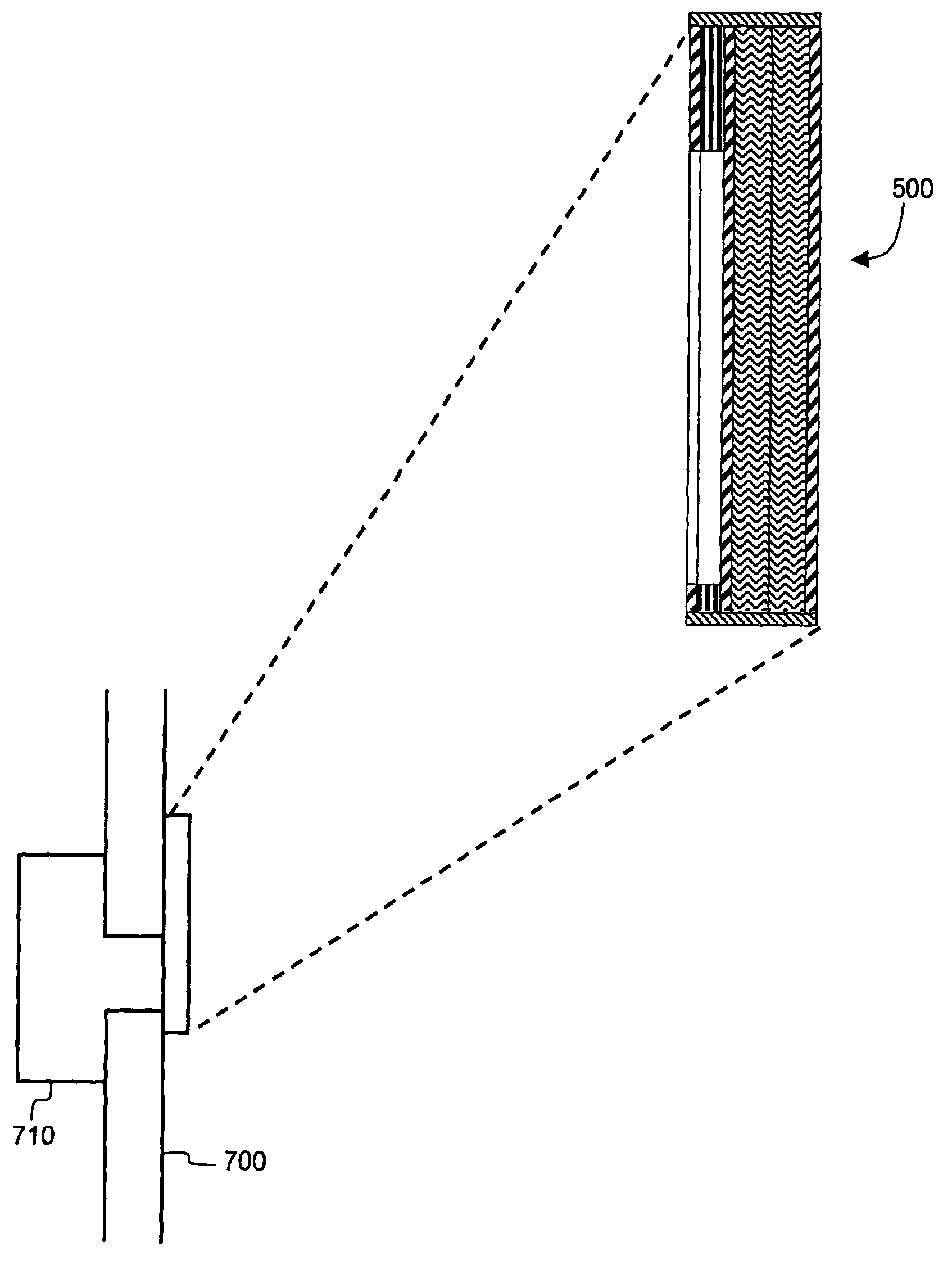
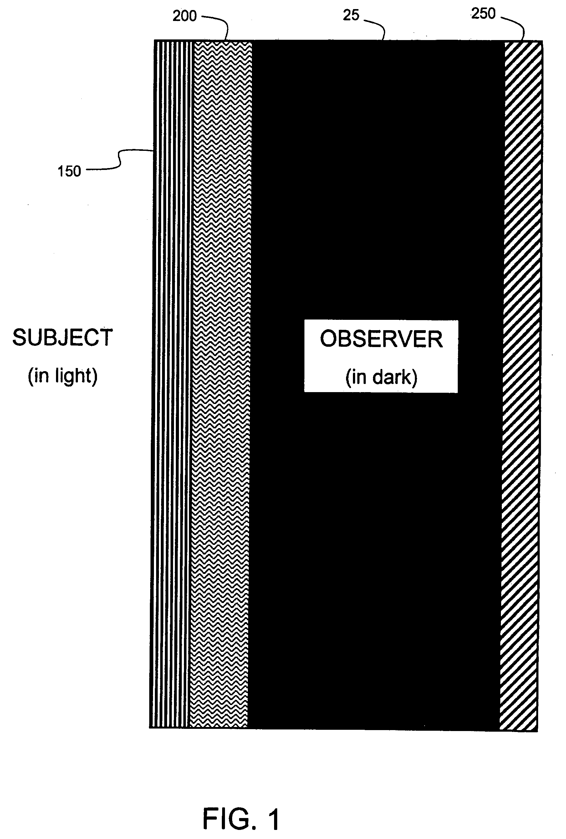
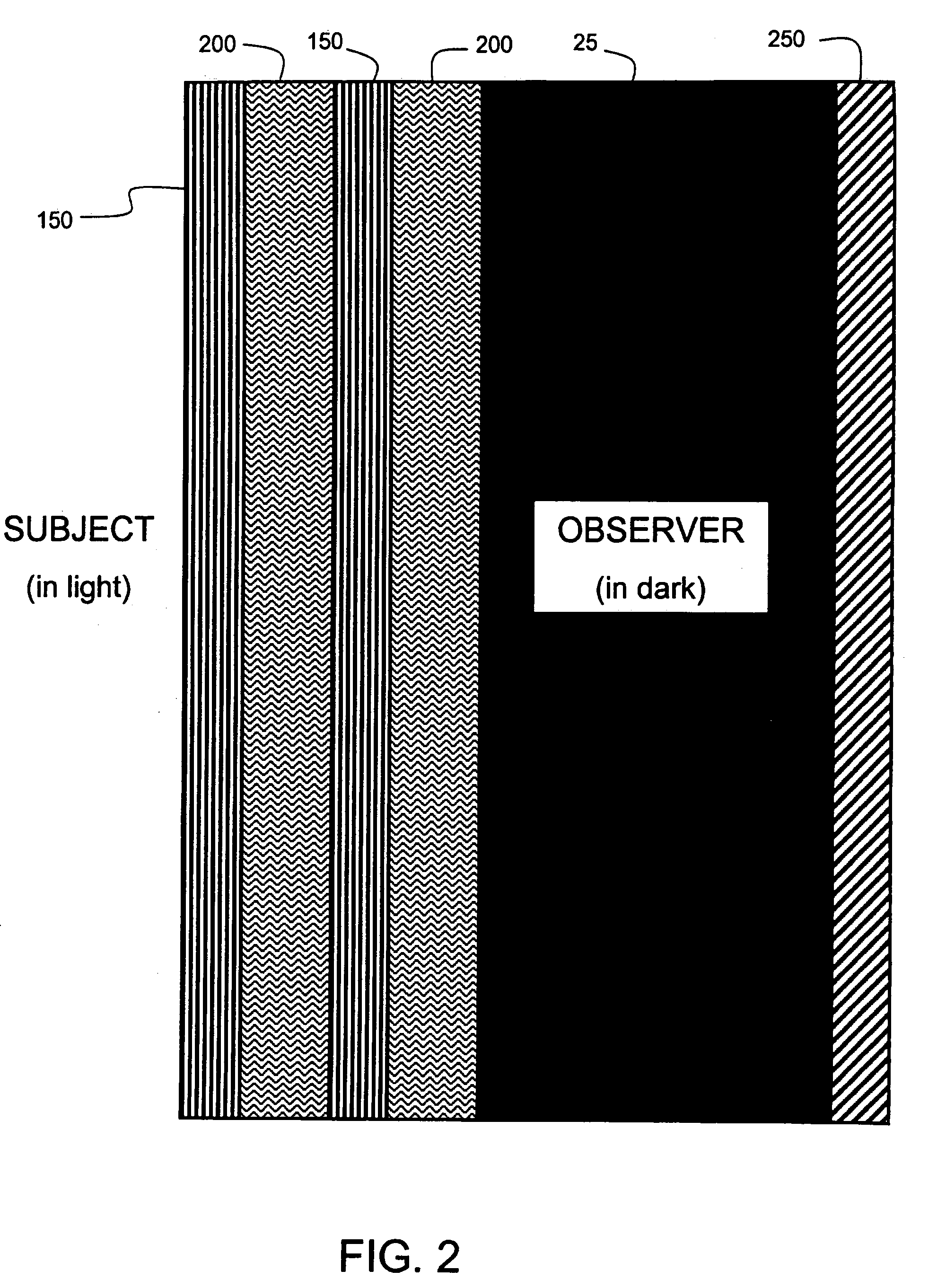
[0021]An embodiment of the present invention is shown in cross-section in FIG. 1. On the left side is shown the subject, and on the right side the observer. As indicated in the figure, in an embodiment of the invention the observer is in an area of darkness 25 relative to the subject. The surveillance window is installed with a linear polarizer 150 facing the subject, a quarter-waveplate 200 facing the observer, and a reflecting surface 250 on the observer side. An optically clear adhesive...


PUM


Abstract

A surveillance window including at least one set of linear polarizer and quarter-waveplate and a reflecting surface. The surveillance window appears dull and opaque to a subject, while allowing a relatively high percentage of light to be transmitted to an observer. Various enhancements including an illuminator and detector, camouflaging, fire resistance, and improvements to the opacity are also described.

Description

CROSS-REFERENCE TO RELATED APPLICATIONS[0001]This application claims the benefit of U.S. provisional patent application No. 60 / 331,979 filed Nov. 21, 2001, and U.S. provisional patent application No. 60 / 333,398 filed Nov. 26, 2001, both of which are incorporated by reference in their entirety.FIELD OF THE INVENTION[0002]The present invention relates to the design of optical devices for surveillance. In particular, it relates to a one-way optical window for covert surveillance.BACKGROUND OF THE INVENTION[0003]For the purpose of surveillance or reconnaissance, it is desirable for an observer to be able to see a subject without the subject being able to see the observer. The observer and subject need not be people: the observer might be a camera or other light detecting device; the subject might be anyone or anything that the observer is interested in observing.[0004]Devices have been designed expressly for restricting light incident on them to transmission in one direction only. With ...

Claims


Application Information

Patent Timeline
IPC IPC(8): G02B27/28G02B5/00
CPCG08B13/19626G02B27/28
Inventor BENGOECHEA, XAVIERFINIZIO, FRANCESCOGRICH, RICHARD
Owner THALES AVIONICS INC
Why Eureka
Try Eureka