Damping force variable valve assembly and damping force variable shock absorber including the same

a technology of damping force and valve assembly, which is applied in the direction of shock absorbers, valve operating means/release devices, mechanical devices, etc., can solve problems such as unsatisfactory ride comfort, and achieve the effect of satisfying steering performance and ride comfor

Active Publication Date: 2017-07-27
HL MANDO CORP
View PDF0 Cites 3 Cited by
  • Summary
  • Abstract
  • Description
  • Claims
  • Application Information

AI Technical Summary

Benefits of technology

[0022]The present invention has been made in an effort to solve the above problems and is directed to provide a damping force variable valve assembly that maintains a damping force at a medium level by maintaining a position of a plunger, which is operated by a solenoid, at a fail position without inclination toward a hard mode or a soft mode, upon fail of the solenoid installed in a damping force variable valve, thereby providing satisfactory steering performance and ride comfort, and a damping force variable shock absorber including the damping force variable valve assembly.

Problems solved by technology

However, in the damping force variable shock absorber according to the related art, if the supply of the electric current to the solenoid is stopped (that is, failed) due to an accident such as a disconnection of a power line or the like, the spool and the plunger are positioned such that the damping force variable valve assembly implements only one of the soft mode and the hard mode.
Due to this, the damping force variable shock absorber according to the related art is subjected to deterioration in the steering performance and the behavior stability of the vehicle causing safety problems, or to an unpleasant ride comfort due to an excessive damping force.

Method used


Image

  • Damping force variable valve assembly and damping force variable shock absorber including the same
  • Damping force variable valve assembly and damping force variable shock absorber including the same
  • Damping force variable valve assembly and damping force variable shock absorber including the same

Examples


Embodiment Construction

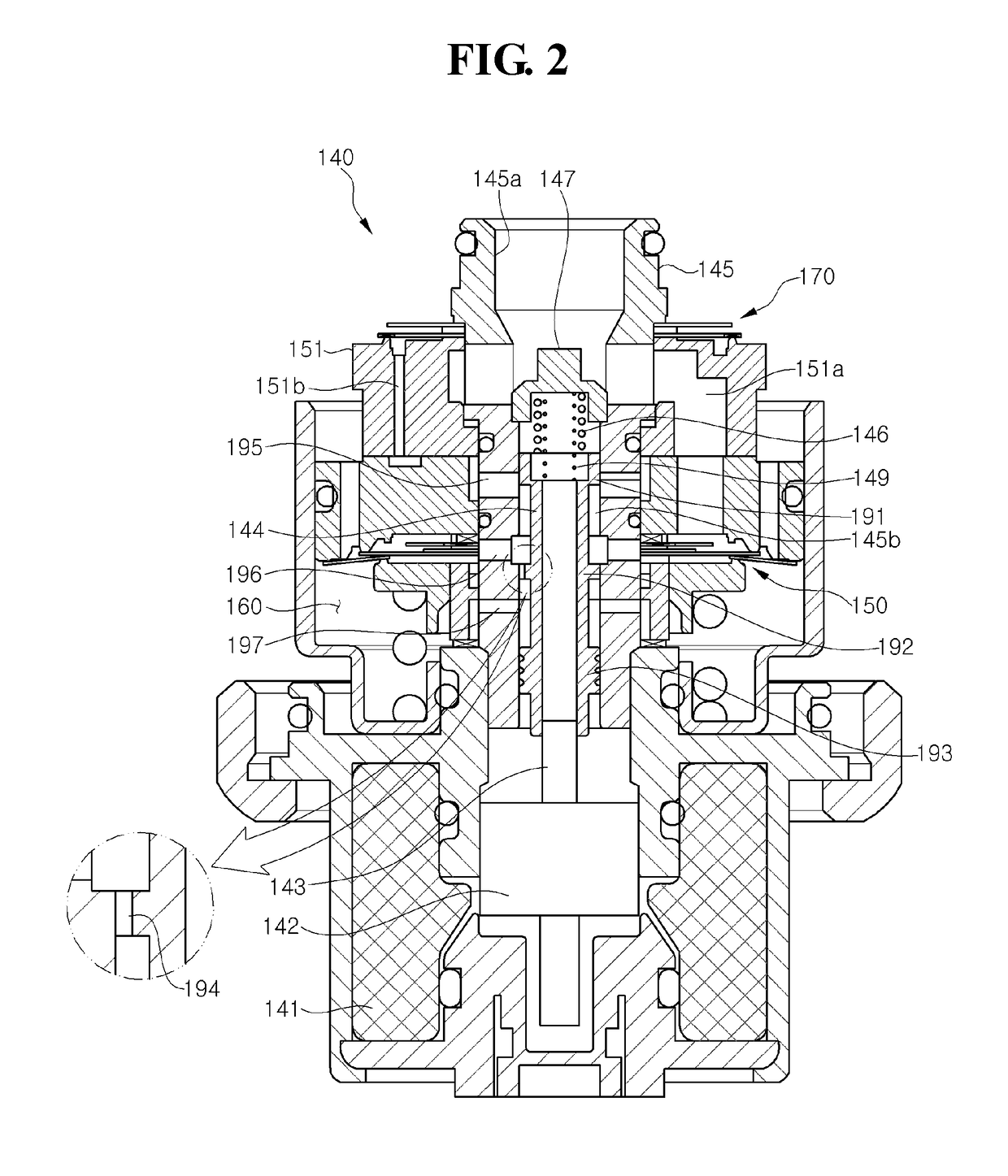
[0033]Hereinafter, a damping force variable valve assembly of a damping force variable shock absorber according to an embodiment of the present invention will be described in detail with reference to the accompanying drawings. For convenience, in the following description given with reference to FIGS. 2 and 3, the same reference numerals as those of FIG. 1 are used to refer to the same elements.

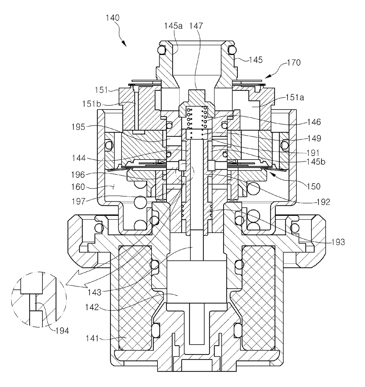
[0034]As illustrated in FIGS. 2 and 3, the damping force variable shock absorber according to an embodiment of the present invention includes a spool position determination member 149 and a communication member 194 communicating a main passage M with a pilot passage P, so as to maintain a damping force at a medium level by locating a spool 144 at a medium position without inclination toward a hard mode or a soft mode, upon fail of a solenoid installed in a damping force variable valve assembly 140.

[0035]The damping force variable valve assembly 140 is provided with oil passages respectively c...


PUM


Abstract

The present disclosure relates to a damping force variable valve assembly, which is installed in a damping force variable shock absorber for adjustment of a damping force of the shock absorber, includes at least: a solenoid that generates a magnetic force when an electric current is supplied thereto; a plunger configured to be moved by the magnetic force of the solenoid; a spool that is moved together with the plunger and change a damping force between a hard mode and a soft mode by changing an inner passage of the damping force variable valve assembly; and a spool position determination member that locates the spool at a fail position, which does not correspond to the hard mode and the soft mode, so as to maintain the damping force of the shock absorber at a medium level between the hard mode and the soft mode upon fail of the solenoid.

Description

CROSS-REFERENCE(S) TO RELATED APPLICATION[0001]This application claims the benefit of Korean Patent Application No. 10-2016-0010096, filed on Jan. 27, 2016, in the Korean Intellectual Property Office, the disclosure of which is incorporated herein in its entirety by reference.BACKGROUND OF THE INVENTION[0002]Field of the Invention[0003]The present invention relates to a damping force variable valve assembly installed in a damping force variable shock absorber, and a damping force variable shock absorber including the same, and more particularly, to a damping force variable valve assembly that maintains a damping force at a medium level by maintaining a position of a spool at a fail position upon fail of a solenoid installed in a damping force variable valve, thereby providing satisfactory steering performance and ride comfort, and a damping force variable shock absorber including the damping force variable valve assembly.[0004]Description of the Related Art[0005]In general, a shock ...

Claims


Application Information

Patent Timeline
Patent Type & Authority Applications(United States)
IPC IPC(8): F16F9/34F16F9/46
CPCF16F9/34F16F2230/24F16F2222/12F16F9/466F16K31/0668
Inventor JUNG, KI DONHWANG, MYEONG SU
Owner HL MANDO CORP
Why Eureka
Try Eureka