Medical coupling and medical system comprising medical coupling
a technology of medical coupling and medical system, which is applied in the field of medical coupling, can solve the problems of tube exerting permanent loosening torque on the thread, the screw connection becoming unscrewed, etc., and achieves the effect of reducing set-up times, improving user friendliness, and preventing bloodlines from twisting
- Summary
- Abstract
- Description
- Claims
- Application Information
AI Technical Summary
Benefits of technology
Problems solved by technology
Method used
Image
Examples
first embodiment
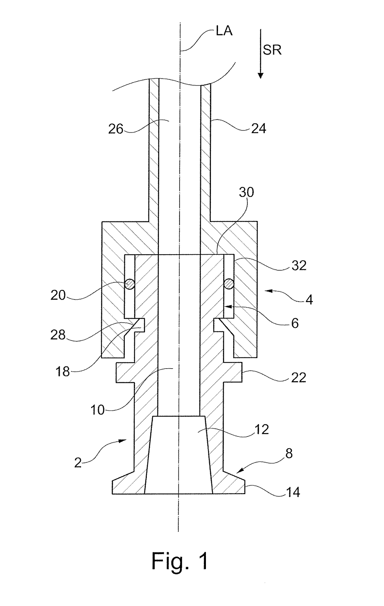
[0049]FIG. 1 illustrates a medical coupling according to aspects of the invention in which a substantially cylindrical adapter 2 and a coupling sleeve 4 are connected to each other. The adapter 2 includes a male coupling portion or, respectively, first coupling portion 6 on its end facing the coupling sleeve 4 and includes a first fastening portion 8 on the other end facing away from the coupling sleeve 4. In addition, the adapter 2 includes a continuous first passage 10 conically widening in the direction away from the coupling sleeve 4. In other words, a first female Luer lock internal cone 12 is formed. Furthermore, at the end of the first fastening portion 8 facing away from the coupling sleeve 4 a first external thread portion or first thread portion 14 is formed. Via the first female Luer lock internal cone 12 and the first thread portion 14 the adapter 2 can be fastened to a medical apparatus or device 16 (not shown in FIG. 1) such as a dialyzer or a machine for extracorporea...
second embodiment
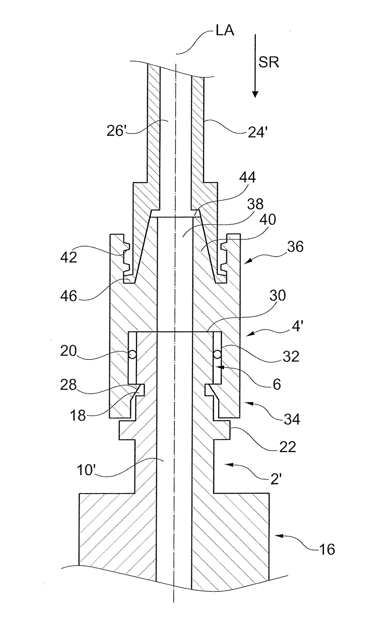
[0055]In the second embodiment, the adapter 2′ is formed integrally with the medical apparatus 16. In other words, the adapter 2′ rather is an extension of the medical apparatus 16 at the end of which facing the coupling sleeve 4′ the first coupling portion 6 is formed as male coupling portion.
[0056]In the second embodiment the coupling sleeve 4′ acts as a connector and thus connects the tube 24′ to the medical apparatus 16. The coupling sleeve 4′ comprises at its end facing the medical apparatus 16 a female coupling portion or, respectively, second coupling portion 34 and at its end facing the tube 24′ comprises a second fastening portion 36. The connection of the adapter 2′ and the coupling sleeve 4′ and, respectively, the first coupling portion 6 and the second coupling portion 34 is made analogously to the first embodiment.
[0057]In the coupling sleeve 4′ moreover a continuous third passage 38 is formed along the longitudinal axis LA. The second fastening portion 36 is a Luer loc...
third embodiment
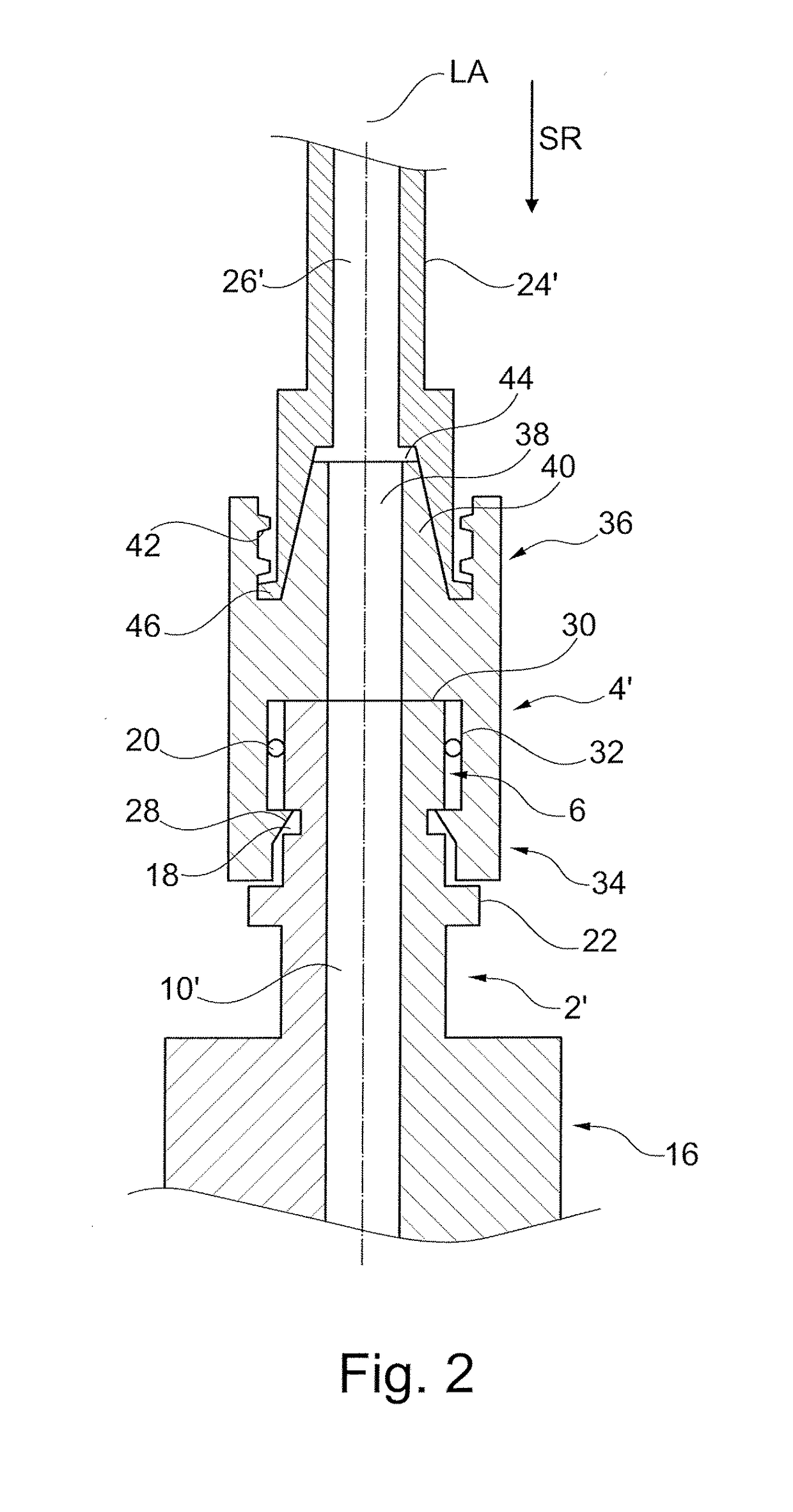
[0062]In the third embodiment, the coupling sleeve 4″ additionally includes a release device 48 comprising a lever 50 and a pin 52. In the locked state as shown in FIG. 3 the lever 50 is arranged in parallel to the longitudinal axis LA and the pin 52 is arranged perpendicularly to the longitudinal axis LA. The lever 50 is articulated at its end facing the adapter 2″ to an end of the pin 52 facing away from the adapter 2″. Furthermore, the release device 48 is provided in a recess 54 of the coupling sleeve 4″ and is articulated to the coupling sleeve 4″ via a pivoting point 56.
[0063]In order to be able to connect the coupling sleeve 4″ to the adapter 2″ the lever 50 has to be moved inwardly in the radial direction at its end facing away from the adapter 2″. In this way the pin 52 is moved outwardly in the radial direction and the coupling sleeve 4″ can be slipped in the sliding direction SR onto the adapter 2″ and, respectively, the first coupling portion 6″. As soon as a front bound...
PUM
 Abstract
Description
Claims
Application Information
 - R&D
- Intellectual Property
- Life Sciences
- Materials
- Tech Scout
- Unparalleled Data Quality
- Higher Quality Content
- 60% Fewer Hallucinations
Browse by: Latest US Patents, China's latest patents, Technical Efficacy Thesaurus, Application Domain, Technology Topic, Popular Technical Reports.
© 2025 PatSnap. All rights reserved.Legal|Privacy policy|Modern Slavery Act Transparency Statement|Sitemap|About US| Contact US: help@patsnap.com


