
Pressure sensor containing mechanically deforming elements

a technology of pressure sensor and deformation element, which is applied in the direction of force transducer, force/torque/work measurement apparatus, measurement device, etc., can solve the problems of brush overloaded, reduced insulation resistance, burnt,

Inactive Publication Date: 2017-08-03
MERSEN BENELUX BV
View PDF4 Cites 16 Cited by
  • Summary
  • Abstract
  • Description
  • Claims
  • Application Information

AI Technical Summary

Benefits of technology

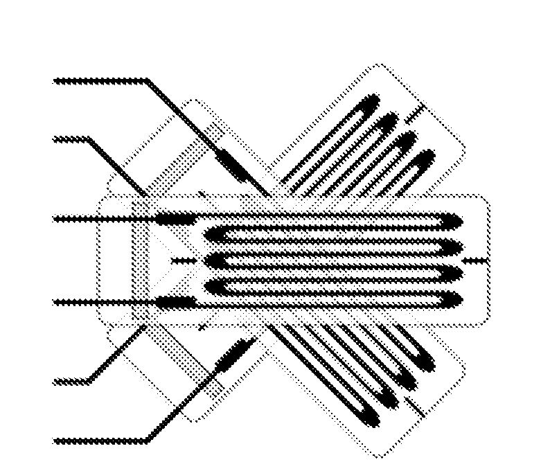
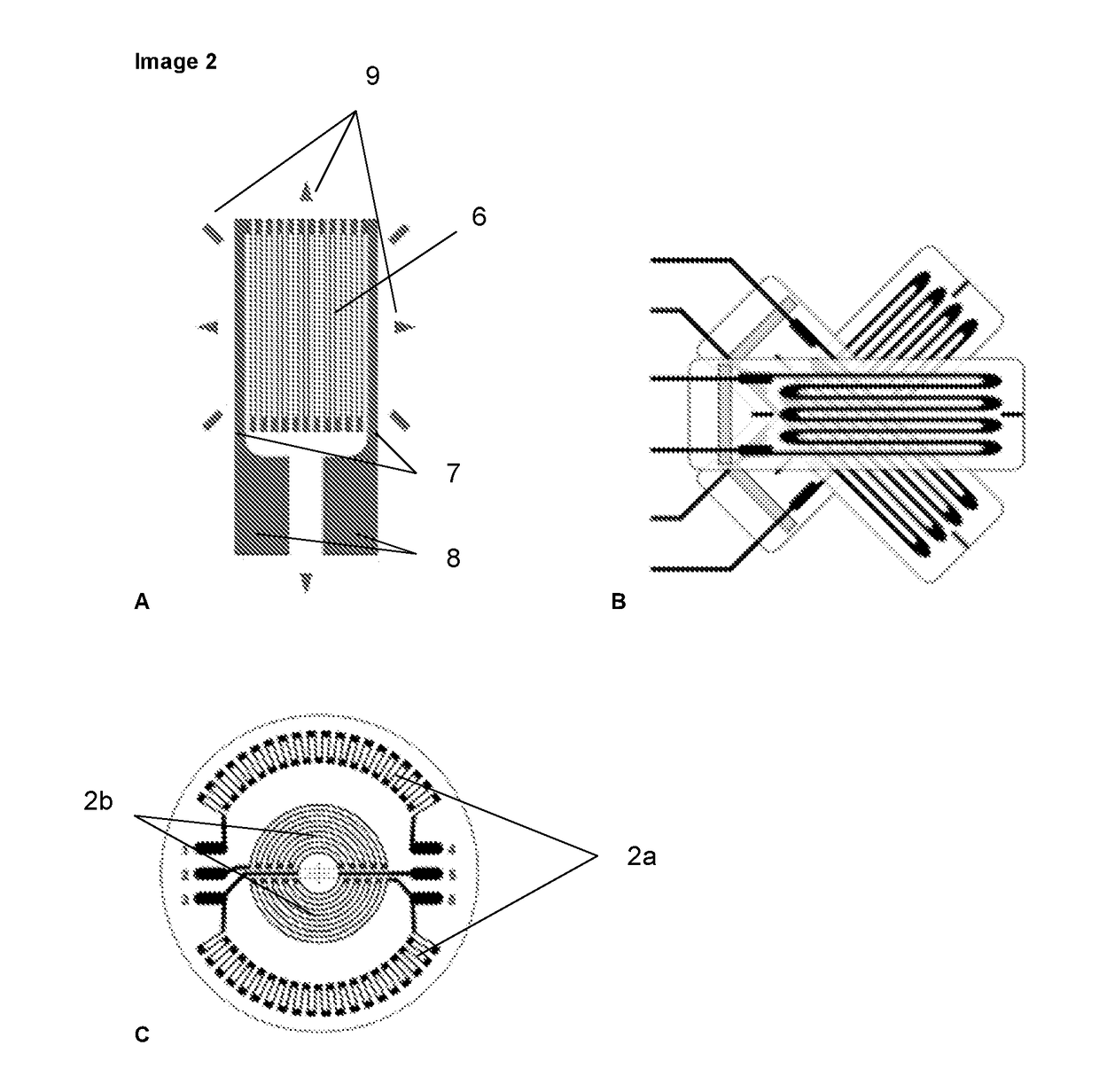
The invention is a sensor that can measure pressure between two surfaces, such as a brush and a slip ring, with a thin and flexible mechanism. The sensor has a target that is suspended by mechanically deformable elements, which detect the shearing of these elements when pressure is applied. The sensor is much thinner and flatter than existing sensors, making it suitable for measuring pressure in the μg-mg range. The sensor also has measuring strips that can detect the deformation of the mechanically deformable elements and the surrounding side or target. This configuration allows for a stable pressure measuring sensor with a thin measuring zone.

Problems solved by technology

In case of the resilience being too high, the brushes and the slip ring or collector wears too quickly (that causes contamination and decreases the insulation resistance).
In case of the resilience being too low, bad contact, arcing and degradadation due to sparking develops, which leads to damage.
If pressure is mutually unequal, the power distribution will become proportionally unbalanced and that, in the first instance, will cause the brushes to wear irregularly and complicate maintenance and, in a further phase, cause some of the brushes to become overloaded and burn with all the associated consequences (could even lead to significant engine damage).
However, the space here is extremely limited.
In view of the large variation in the embodiments of the carbon brush holders and the large range of the pressures to be measured, the existing probes are always too large to be able to use them at the ideal places (between the brush and its contact surface, for example, between the brush and the slip ring).
The range of these probes is frequently limited causing a need for different probes as a function of the pressure to be measured.

Method used


Image

  • Pressure sensor containing mechanically deforming elements
  • Pressure sensor containing mechanically deforming elements
  • Pressure sensor containing mechanically deforming elements

Examples


Embodiment Construction

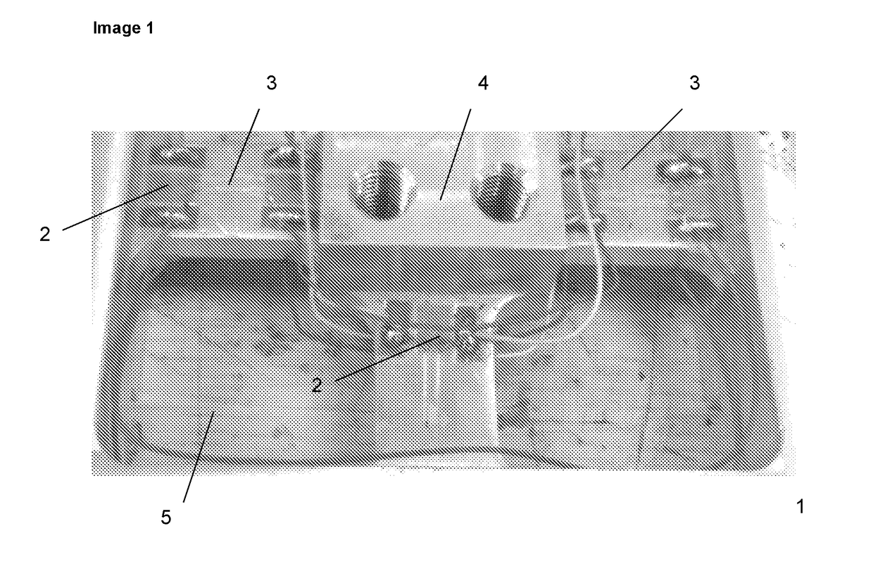
[0003]This invention has the aim of offering a sensor (1) that allows for measuring the pressure force between the contact surface, for example the contact surface between a slip ring (15) and the brush (14), and that is therefore characterized by the fact that the sensor is thinner than 4mm, and has nonetheless been fitted with a target (4) (also referred to as the measuring point or the pressure platform), which has been suspended, by means of mechanically deformable section (3), in a recess (5) in the sensor, and by which this sensor is fitted with one or more measuring strips (2), which has / have been designed as such that it / they can detect the shearing of, of the mechanically deformable section under pressure.

[0004]In contrast to existing measuring sensors, as for example shown in image 1, the measuring strips (2) in this invention are not just lying on the mechanically deformable section (3) located between the measuring point (target) and the perimeter of the sensor. As becom...


PUM

PropertyMeasurementUnit
thicknessaaaaaaaaaa
total thicknessaaaaaaaaaa
sizeaaaaaaaaaa

Abstract

The invention has the objective of offering a sensor the allows for measuring the pressure force of the springs on the carbon brushes as well as the actual brush pressure on its contact surface. This is obtained by measuring between the carbon brush, and there is limited space through its holder, and the contact surface and is therefore characterized by the fact that the sensor is thinner than 4 mm, and that it is provided with a target (4) which is suspended in the sensor (1) by means of a mechanically deformable section (3), and where the sensor is fitted with one or more strain gauges (2) that is / are set up as such that it can detect the shearing of the mechanical deformable measuring section under pressure. In contrast to the existing measuring sensors, the measuring strips also connect the suspension points of the mechanically deformable elements with the sensor and / or the suspended target or measuring point through which sensitivity increases and makes the sensor useful for such applications.

Description

BACKGROUND TO THE INVENTION[0001]In case of carbon brush electric machines, such as engines, alternators, generators or others, the brushes are pushed against their contact surfaces, such as slip rings or collectors, via a spring. This resilience is required to ensure the engine's proper functioning. In case of the resilience being too high, the brushes and the slip ring or collector wears too quickly (that causes contamination and decreases the insulation resistance). In case of the resilience being too low, bad contact, arcing and degradadation due to sparking develops, which leads to damage. If pressure is mutually unequal, the power distribution will become proportionally unbalanced and that, in the first instance, will cause the brushes to wear irregularly and complicate maintenance and, in a further phase, cause some of the brushes to become overloaded and burn with all the associated consequences (could even lead to significant engine damage). It is therefore important to mon...

Claims


Application Information

Patent Timeline
Patent Type & Authority Applications(United States)
IPC IPC(8): G01L5/00G01L1/22
CPCG01L5/0085G01L5/0057G01L5/0004G01L1/2243
Inventor OVAERE, PETERSCHEPENS, PIETER-JAN
Owner MERSEN BENELUX BV
Learn More