
Fire and smoke containment services transit unit and an associated method

a transit unit and fire containment technology, applied in electrical equipment, medical science, dental surgery, etc., can solve the problems of poor insulation performance and drawbacks of the approach, and achieve the effect of improving the insulation performance and reducing the risk of fir

Active Publication Date: 2017-08-17
RAKMAN INT
View PDF1 Cites 8 Cited by
  • Summary
  • Abstract
  • Description
  • Claims
  • Application Information

AI Technical Summary

Benefits of technology

The present invention provides a fire and smoke containment services transit unit that can be mounted within a hole in a barrier, allowing for the passage of at least one service through the unit. The unit includes an intumescent material that swells upon heat exposure, and a casing with low thermal conductivity to prevent heat transfer. The method of routing services through the transit unit involves positioning the unit within the hole in the barrier and threading the service through the unit. The invention also allows for the alteration of the service or services, with the use of foam to provide a friction fit around the unit. The technical effects of the invention include improved fire and smoke containment, reduced heat transfer, and improved service alteration.

Problems solved by technology

It has been appreciated by the inventor of the present application that typical prior art transit units, such as the Abesco CT120 and CT240 cable transit units for example, perform relatively well in relation to the integrity characteristics; however they typically perform fairly poorly in relation to the insulation characteristics.
However, it has been appreciated by the inventor of the present application that this approach suffers from draw backs when attempting to retro-fit additional services through the transit unit (i.e. at some later time after the initial installation has been completed).

Method used


Image

  • Fire and smoke containment services transit unit and an associated method
  • Fire and smoke containment services transit unit and an associated method
  • Fire and smoke containment services transit unit and an associated method

Examples


Embodiment Construction

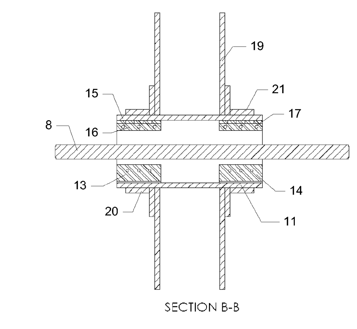
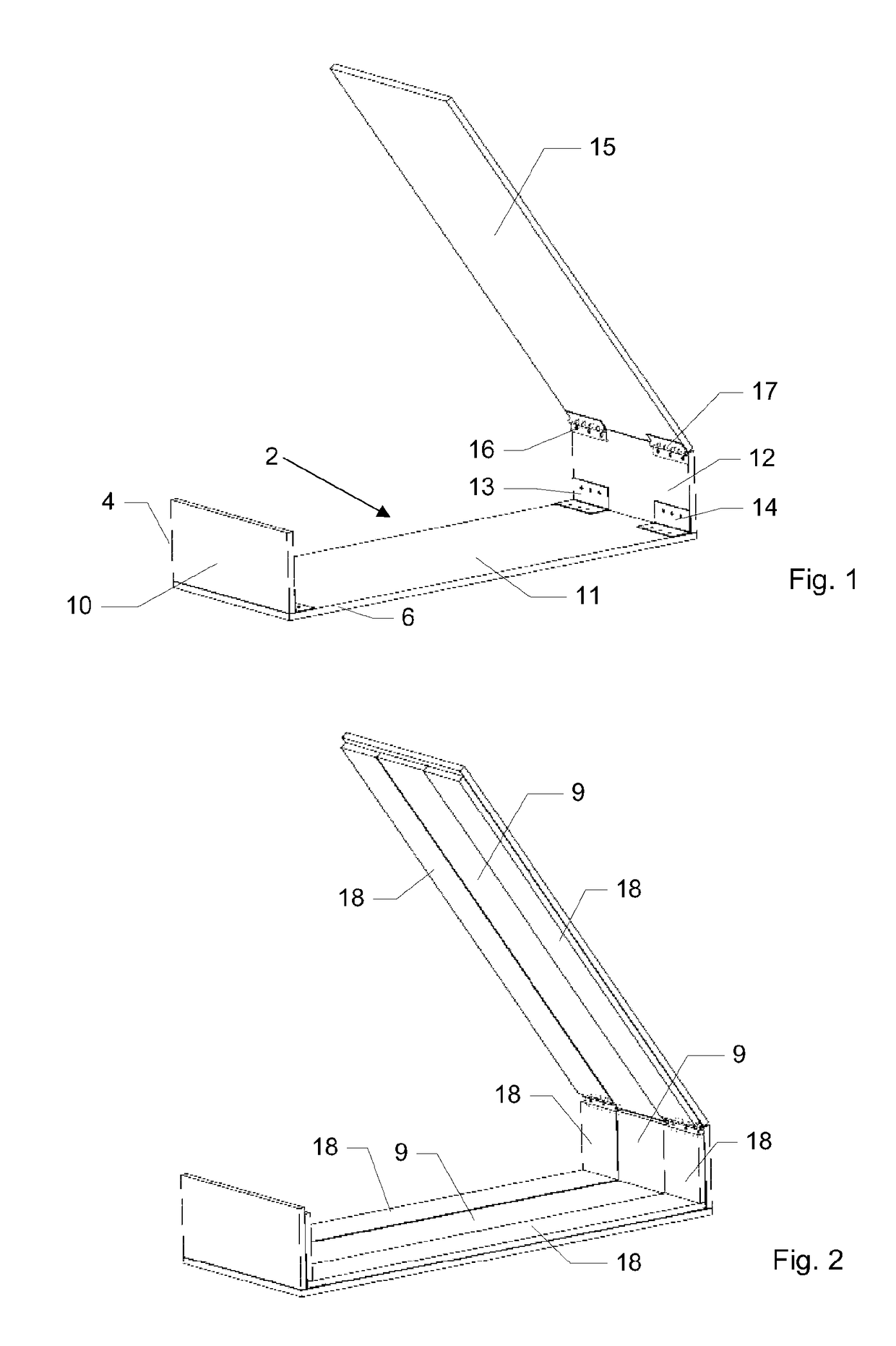
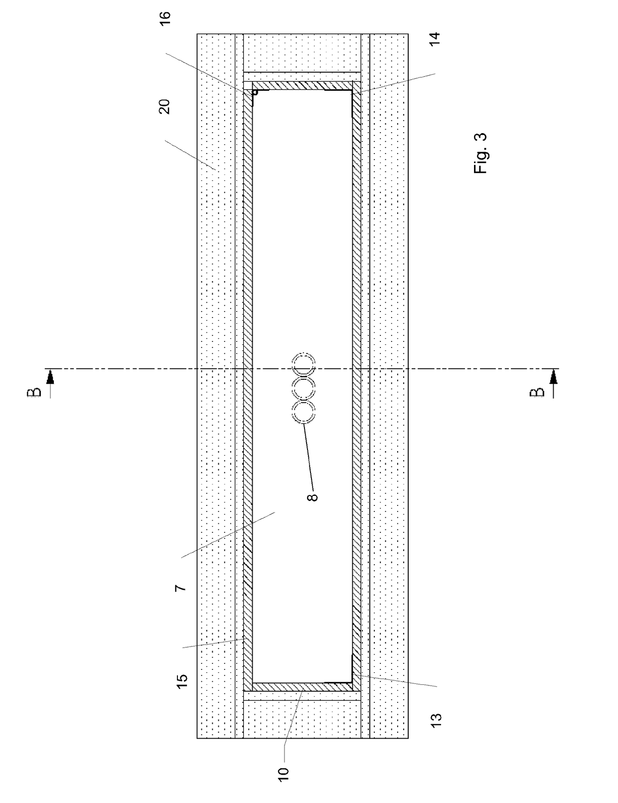
[0037]Referring to the figures, the fire and smoke containment services transit unit 1 includes a casing 2, which is constructed from a material having a thermal conductivity of less than 5 watts per meter per Kelvin and more preferably less than 0.5 watts per meter per Kelvin. Examples of suitable materials include calcium silicate boards, such as Orbit FR Board, which has a thermal conductivity of approximately 0.137 watts per meter per Kelvin or Maxilite board, which has a thermal conductivity of approximately 0.14 watts per meter per Kelvin. Another example of a suitable material is Promatect H board, which has a thermal conductivity of approximately 0.242 W / m.K, as sold by Promat Australia Pty Ltd in Adelaide, South Australia. Further examples include Vermiclux and Supalux, which each have a conductivity of less than 5 W / m.K, or Monolux, which has a thermal conductivity of approximately 0.18 W / m.K, as sold by Intumex Asia Pacific in Northmead, NSW, Australia. Another example is...


PUM


Abstract

The fire and smoke containment services transit unit includes a casing constructed from a material having a thermal conductivity of less than 5 watts per meter per Kelvin. The casing defines a first opening at a first end and a second opening at the second end. Intermediate the first and second end is the internal volume that is encased by the casing. The internal volume and each of the openings are sized to allow services such as cables, pipes, etc. to be threaded through the services transit unit. An intumescent material is housed centrally within the internal volume. Prior to exposure to the heat of a fire, the intumescent material maintains a slim profile. However, when the transit unit is exposed to the heat associated with a building fire, it swells and thereby seals the internal volume against the passage of fire, smoke or heated gases through the transit unit.

Description

TECHNICAL FIELD[0001]The present invention relates to a fire and smoke containment services transit unit and an associated method. Embodiments of the present invention find application in the field of passive fire protection.BACKGROUND ART[0002]Any discussion of documents, acts, materials, devices, articles or the like which has been included in this specification is solely for the purpose of providing a context for the present invention. It is not to be taken as an admission that any or all of these matters form part of the prior art base or were common general knowledge in the field relevant to the present invention as it existed in Australia or elsewhere before the priority date of this application.[0003]Prior art transit units are known whereby services, such as cables, pipes, etc., are routed through barriers (for example walls, floors, ceilings and service shafts), in a manner that provides a degree of passive fire protection. It is desirable for such transit units to exhibit ...

Claims


Application Information

Patent Timeline
Patent Type & Authority Applications(United States)
IPC IPC(8): A62C2/06H02G3/04F16L5/02H02G3/22
CPCA62C2/065F16L5/02H02G3/0412H02G3/22F16L5/04
Inventor RAKIC, JOHN
Owner RAKMAN INT
Learn More