Optical chiral fiber isolator and method of fabrication thereof

a technology isolator, which is applied in the field of optical chiral fiber isolators, can solve the problems of inconvenient manufacturing, low production efficiency, and high cost of conventional optical isolators, and achieves the effect of convenient and relatively inexpensive manufacturing, installation, use and maintenan

Active Publication Date: 2017-11-23
CHIRAL PHOTONICS
View PDF4 Cites 13 Cited by
  • Summary
  • Abstract
  • Description
  • Claims
  • Application Information

AI Technical Summary

Benefits of technology

[0019]comprises a substantially in-fiber (i.e. not “bulk”) physical profile that facilitates fabrication, installation and utilization thereof;
[0020]can be readily preconfigured with desired characteristics / parameters without any need for adjustment and / or tuning;
[0021]has a high degree of physical and thermal stability, and resistance to effects of physical stress and / or temperature variations on the performance thereof;
[0023]is easy and relatively inexpensive to manufacture, install, use, and maintain.
[0024]In essence, the inventive optical in-fiber chiral fiber isolator accomplishes the above goals by utilizing specially configured “in-fiber” chiral fiber elements for each component thereof that enable the novel isolator to achieve a high degree of performance, while maintaining a number of significant advantages over previously known bulk device optical isolator solutions.

Problems solved by technology

While in essence, the above-described commonly known prior art optical isolator generally serves its purpose well in most commercial / industrial / scientific applications, such isolators suffer from a number of significant disadvantages.
Conventional optical isolators are also relatively expensive to manufacture, use, maintain and / or to troubleshoot.
Furthermore, there are a total of six points of contact interfaces between the input optical element, the input polarizer, the rotator, the output polarizer, and the output optical element—each of these interface points are a potential source of signal loss and / or damage for the entry / exit interfaces of each prior art isolator elements.
While attempts to address this issue, by coating each glass interface surface with anti-reflective coating or by tilting the optical components to form sufficient angles between interface surfaces to reduce / avoid back reflection, from an optical power-handling viewpoint, the interfaces where light signals exit and enter glass surfaces remain the most likely candidates for damage from the signals.
Finally, the multi-element construction and need to maintain proper alignment between all the elements makes conventional optical isolators unstable and unreliable in conditions where such isolators may be subjected to physical stress and / or to temperature variations.

Method used


Image

  • Optical chiral fiber isolator and method of fabrication thereof
  • Optical chiral fiber isolator and method of fabrication thereof
  • Optical chiral fiber isolator and method of fabrication thereof

Examples


Embodiment Construction

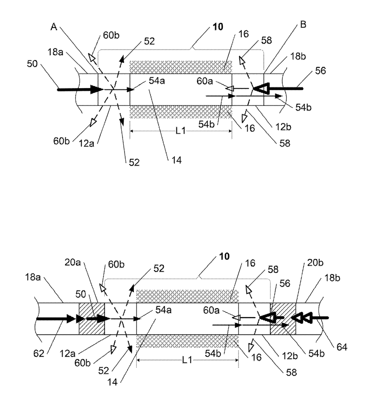
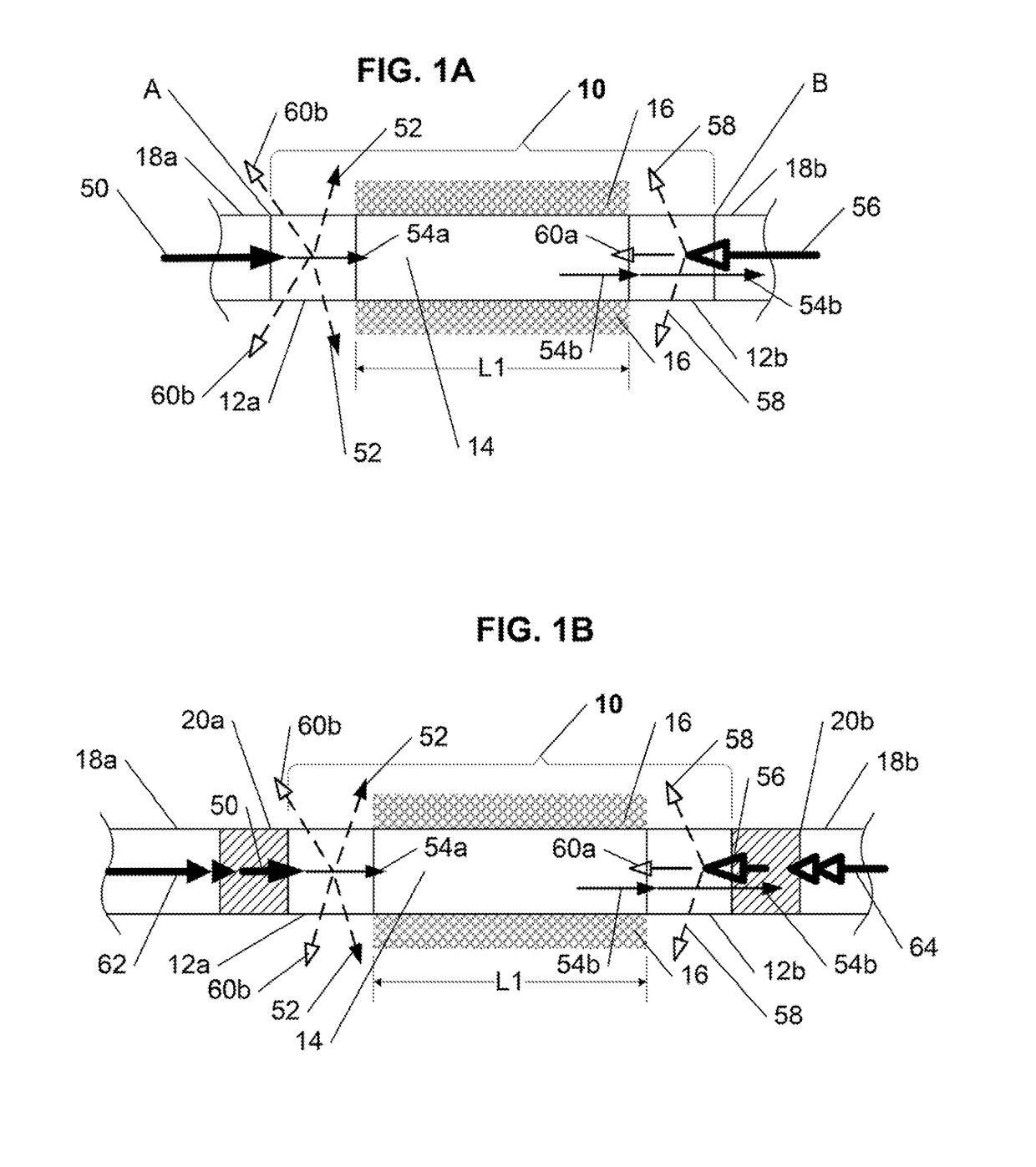
[0026]The present invention is directed to a optical in-fiber chiral fiber isolator capable of transmitting a signal (e.g., light) of a predetermined desired optical polarization in a forward direction therethrough, while rejecting all signals traveling in a backward direction therethrough.

[0027]In summary, in its first exemplary embodiment, the optical chiral fiber isolator includes a chiral magneto-optical fiber having a helical pitch profile, a birefringence profile, and an effective Verdet constant profile, at least a portion of which is exposed to a magnetic field of a predetermined magnetic field profile (generated by a proximal magnetic field source), where the magnetic field profile, the chiral pitch profile, the birefringence profile, and the effective Verdet constant profile are selected and configured such that the inventive isolator is capable of transmitting a signal of a predetermined optical polarization in a direction from its input end toward its output end, and to ...


PUM

PropertyMeasurementUnit
birefringenceaaaaaaaaaa
Verdet constantaaaaaaaaaa
magneticaaaaaaaaaa

Abstract

The present invention provides an optical in-fiber chiral fiber isolator, capable of transmitting a signal of a predetermined optical polarization in a forward direction therethrough, while rejecting all signals traveling in a backward direction therethrough, and a method of fabrication thereof. In one exemplary embodiment, the inventive optical chiral fiber isolator includes a chiral magneto-optical fiber having a helical pitch profile, a birefringence profile, and an effective Verdet constant profile, at least a portion of which is exposed to a magnetic field of a predetermined magnetic field profile (generated by a proximal magnetic field source), where the magnetic field profile, the chiral pitch profile, the birefringence profile, and the effective Verdet constant profile are selected and configured such that the inventive isolator is capable of transmitting a signal of a predetermined optical polarization in a direction from its input end toward its output end, and to reject all signals in a direction from its output end to its input end.

Description

CROSS REFERENCE TO RELATED APPLICATIONS[0001]The present patent application is a continuation of U.S. application Ser. No. 12 / 492,984, entitled “Optical Chiral Fiber Isolator and Method of Fabrication Thereof,” filed Jun. 26, 2009, which claims priority benefit from the commonly assigned co-pending U.S. provisional patent application 61 / 075,755, entitled “Optical Chiral Fiber Isolator and Method of Fabrication Thereof”, filed Jun. 26, 2008.FIELD OF THE INVENTION[0002]The present invention relates generally to optical isolators, and more particularly to an in-fiber optical chiral fiber isolator that overcomes the drawbacks of all previously known polarization-sensitive optical / Faraday isolators.BACKGROUND OF THE INVENTION[0003]Optical isolators (sometimes called “optical diodes”), and particularly polarization-dependent optical isolators (also referred to as “Faraday isolators”) are commonly utilized optical components which allow the transmission of light in only one predetermined d...

Claims


Application Information

Patent Timeline
Patent Type & Authority Applications(United States)
IPC IPC(8): G02F1/095H01F7/02
CPCH01F7/0273G02F1/0955
Inventor KOPP, VICTOR IL'ICHZHANG, GUOYIN
Owner CHIRAL PHOTONICS
Why Eureka
Try Eureka