DC circuit breaker

a circuit breaker and direct current technology, applied in the direction of electronic switching, transmission, pulse technique, etc., can solve the problems of inability to slow interruption speed, and arc generation in the mechanical switch, so as to improve the reliability of operation, easily and quickly extinguish the arc, and reliably interrupt the fault current

Active Publication Date: 2017-12-14
HYOSUNG HEAVY IND CORP
View PDF4 Cites 8 Cited by
  • Summary
  • Abstract
  • Description
  • Claims
  • Application Information

AI Technical Summary

Benefits of technology

[0022]As described above, the present invention can reliably interrupt a fault current by easily and rapidly extinguishing an arc when the arc is generated during a switching operation of a mechanical switch provided in a DC circuit breaker
[0023]In addition, the DC circuit breaker according to the present invention can interrupt fault currents flowing in both forward and backward directions with a single circuit.
[0024]In addition, the DC circuit breaker according to the present invention can lower a transient recovery voltage (TRV) applied between two contacts thereof immediately after a fault current is interrupted, thereby improving operation reliability for interruption of a fault current.

Problems solved by technology

However, when the mechanical switch is opened to interrupt a fault current, an arc is generated in the mechanical switch due to a high voltage applied thereto.
Therefore, there is a problem that the fault current is not reliably interrupted.
However, the conventional DC circuit breakers have a problem that interruption speed is slow because the resonance current is generated through multiple resonance cycles.
In addition, the conventional DC circuit breakers have a problem that they have a high transient recovery voltage (TRV), which is a voltage applied between two contacts of a circuit breaker after a fault current is interrupted.
However, since conventional DC circuit breakers have a high TRV, a dielectric breakdown between the contacts is likely to occur in the DC circuit breakers.

Method used


Image

  • DC circuit breaker
  • DC circuit breaker
  • DC circuit breaker

Examples


Embodiment Construction

[0028]Hereinafter, a preferred embodiment of the present invention will be described with reference to the accompanying drawings. In addition, descriptions of known functions or constructions which have been deemed to unnecessarily obscure the gist of the present invention will be omitted below.

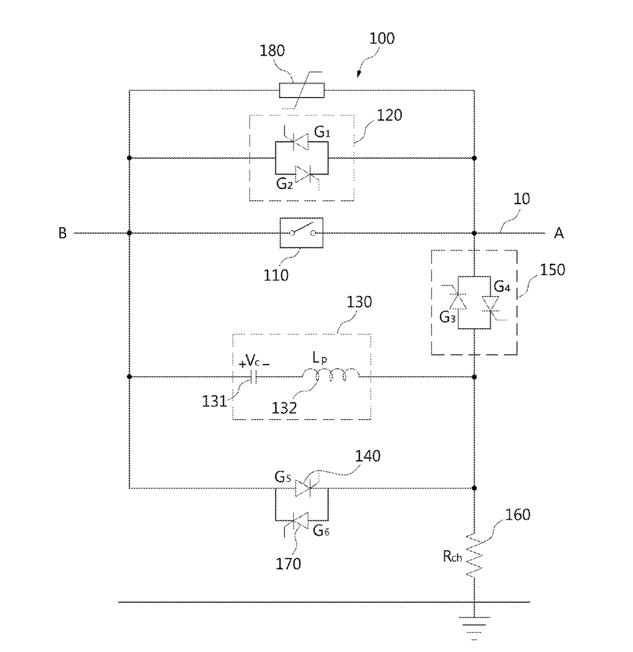
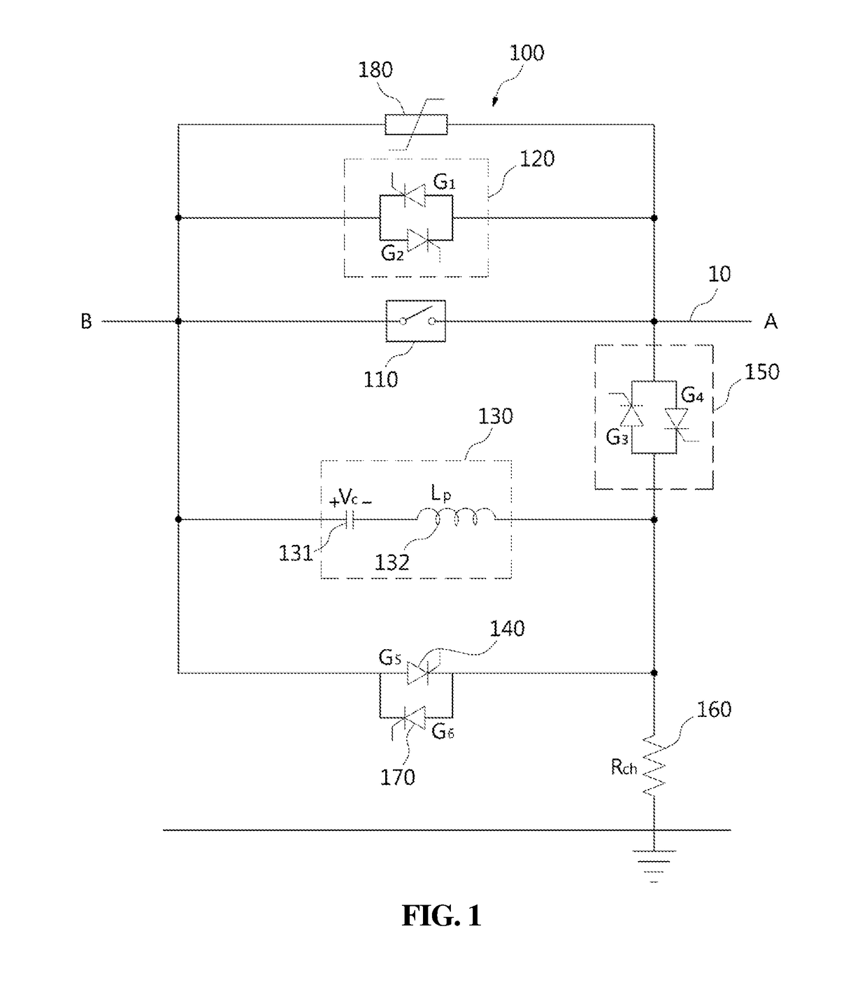
[0029]FIG. 1 is a configuration diagram of a DC circuit breaker according to one embodiment of the present invention.

[0030]With reference to FIG. 1, according to one embodiment of the present invention, a direct current (DC) circuit breaker 100 includes a mechanical switch 110 installed on a DC transmission line 10 connecting a first side (A side) and a second side (B side) to each other. The mechanical switch 130 functions to block the DC transmission line 10 to prevent a fault current from being supplied to a faulty system when a fault occurs at the first side (A side) or the second side (B side). To this end, the mechanical switch 110 is closed in normal condition but opened to interrupt a...


PUM


Abstract

Disclosed is a DC circuit breaker capable of interrupting fault currents flowing in both forward and backward directions. The DC circuit breaker includes: a mechanical switch installed on a DC transmission line and being opened to interrupt a current in the DC transmission line when a fault occurs at one side or remaining side thereof on the DC transmission line; a first bidirectional switching device connected in parallel with the mechanical switch and switching currents flowing in both forward and backward directions; an LC circuit connected in parallel with the mechanical switch and including a capacitor and a reactor connected in series to induce LC resonance; a first unidirectional switching device connected in parallel with the LC circuit and switching a current to induce LC resonance; and a second bidirectional switching device connected in series with the LC circuit and switching currents flowing in both forward and backward directions.

Description

TECHNICAL FIELD[0001]The present invention relates to a direct current (DC) circuit breaker and, more particularly, to a DC circuit breaker capable of interrupting a fault current flowing through a DC transmission line in both directions with respect to a mechanical switch when a fault occurs on the DC transmission line.BACKGROUND ART[0002]A direct current circuit breaker (DC circuit breaker) is used to interrupt a fault current when a fault occurs on a direct current transmission line used as a high voltage transmission line. A direct current transmission line for a high voltage is used as a transmission line for a high voltage of 50 kV or higher of a high voltage direct current (HVDC) transmission system or a transmission line for a medium voltage of 50 kV or lower of a medium voltage direct current (MVDC) distribution system.[0003]A DC circuit breaker is provided with a relatively inexpensive mechanical switch to interrupt a fault current when a fault occurs on a DC transmission ...

Claims


Application Information

Patent Timeline
Patent Type & Authority Applications(United States)
IPC IPC(8): H02H3/18H01H9/54H03K17/56
CPCH02H3/18H01H9/54H03K17/56H01H33/59H04B3/00H01H33/593H01H33/596H02H3/087
Inventor KIM, BYUNG CHOULHONG, JUNG KIHAN, YOUNG SEONG
Owner HYOSUNG HEAVY IND CORP
Why Eureka
Try Eureka