

Rollable Display
a display panel and roll-type technology, applied in the direction of display/control unit casings, electrical apparatus casings/cabinets/drawers, identification means, etc., can solve the problems of low physical durability of thin and lightweight display panels, low reliability and stability of products, and easy damage of display panels
- Summary
- Abstract
- Description
- Claims
- Application Information
AI Technical Summary
Benefits of technology
Problems solved by technology
Method used
Image

Examples
first exemplary embodiment
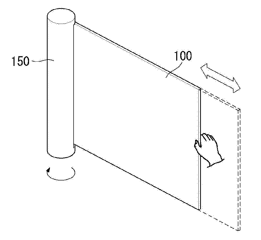
[0096]A rollable display according to a first exemplary embodiment of the present invention is described with reference to FIGS. 12 through 13C. FIG. 12 is a perspective view illustrating a rollable display according to the first exemplary embodiment of the present invention. FIGS. 13A through 13C are views for explaining the operating condition of the rollable display according to the first exemplary embodiment of the present invention.
[0097]Referring to FIG. 12, the rollable display according to the first exemplary embodiment of the present invention comprises a panel roller 150, a flexible display panel 100, a back cover 200, a flexible magnet 250, and a first elastic member 300.
[0098]The panel roller 150 may be approximately cylindrical. That is, a cross-section of the panel roller 150 may be circular. However, the panel roller 150 is not limited to this shape and may take any shape as long as the flexible display panel 100 can be rolled up with ease.
[0099]The panel roller 150 m...
second exemplary embodiment
[0116]A rollable display according to a second exemplary embodiment of the present invention is described below in reference to FIGS. 14 through 19. FIG. 14 is a perspective view illustrating a rollable display according to the second exemplary embodiment of the present invention. FIGS. 15A through 15D are views for explaining the configuration and operation of an elastic structure, according to one embodiment. FIGS. 16 through 19 are views for explaining the operating condition of the rollable display according to the second exemplary embodiment of the present invention.
[0117]Referring to FIG. 14, the rollable display according to the second exemplary embodiment of the present invention comprises a panel roller 150, a flexible display panel 100, a back cover 200, a flexible magnet 250, and an elastic structure 400.
[0118]The panel roller 150 may be approximately cylindrical. That is, a cross-section of the panel roller 150 may be circular. However, the panel roller 150 is not limite...
third exemplary embodiment
[0144]A rollable display according to a third exemplary embodiment of the present invention is described below with reference to FIGS. 20 through 23. FIGS. 20 through 23 are views for explaining a rollable display according to the third exemplary embodiment of the present invention. FIG. 20 and FIG. 22 are enlarged views illustrating the AR area at a side of the rollable display.
[0145]Referring to FIGS. 20 and 21, the rollable display according to the third exemplary embodiment further comprises a support structure 700. The support structure 700 is provided on a side edge of the back cover 200. The side edge extends in a direction (Z-axis) parallel to the direction in which the flexible display panel 100 and the back cover 200 roll up and down.
[0146]The side of the flexible display panel 100 is inserted into internal space provided by connecting the support structure 700 and the back cover 200 together. That is, the support structure 700 is provided in such a way that encloses the f...
PUM
 Abstract
Description
Claims
Application Information